Direct fuel injection engine

a fuel injection and internal combustion engine technology, applied in combustion engines, machines/engines, pistons, etc., can solve the problems of limiting unable to maintain the desired hollow circular cone shape, weak penetration of the fuel stream in the direction of fuel injection, etc., to achieve the effect of restricting the degree of design freedom and extremely small gas flow inside the cylinder

Inactive Publication Date: 2006-09-12
NISSAN MOTOR CO LTD
View PDF40 Cites 5 Cited by
  • Summary
  • Abstract
  • Description
  • Claims
  • Application Information

AI Technical Summary

Benefits of technology

[0009]It has been discovered that with a swirl injection valve as mentioned above, the penetration of the fuel stream is generally weak in the fuel injection direction. Consequently, in order to allow the majority of the injected fuel to hit the surrounding wall surface of the cavity it is necessary to keep the gas flow inside the cylinder extremely small. This requirement greatly restricts the degree of design freedom when designing the engine.

Problems solved by technology

It has been discovered that with a swirl injection valve as mentioned above, the penetration of the fuel stream is generally weak in the fuel injection direction.
This requirement greatly restricts the degree of design freedom when designing the engine.
Thus, depending on the injection timing, it may not be possible to maintain the desired hollow circular cone shape.

Method used


Image

  • Direct fuel injection engine
  • Direct fuel injection engine
  • Direct fuel injection engine

Examples


second embodiment

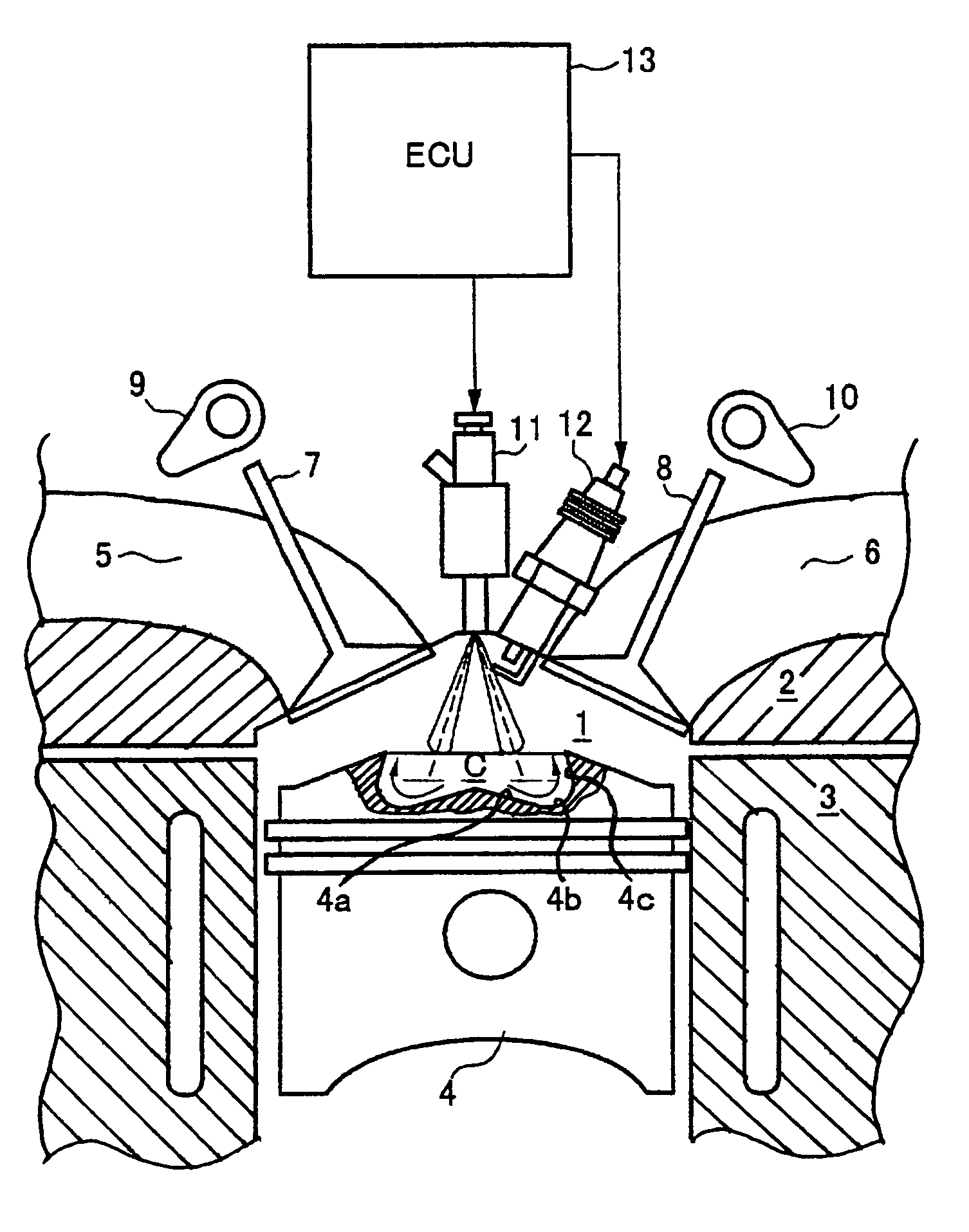
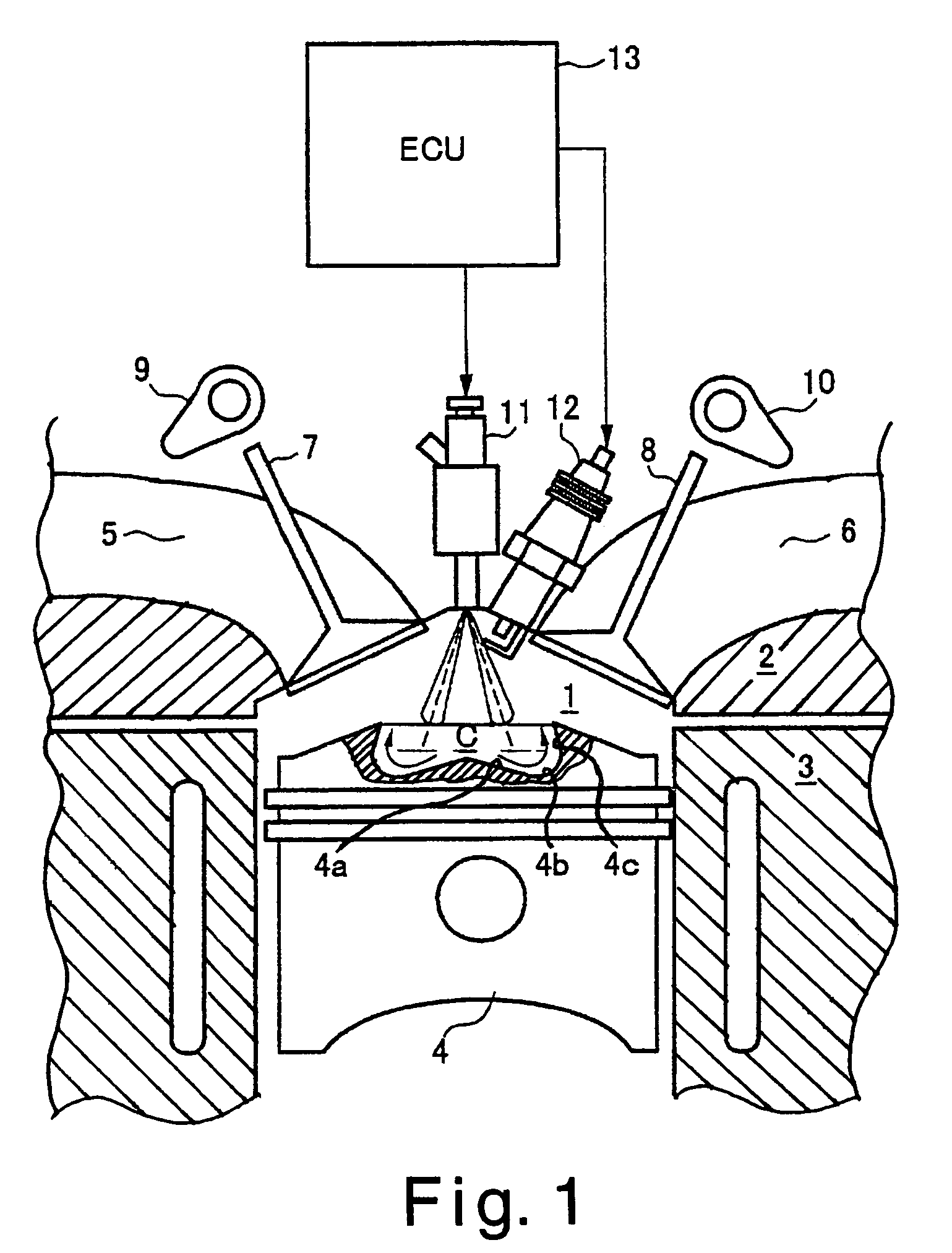
[0059]Referring now to FIGS. 9–16, a schematic view of a direct fuel injection engine invention will be described in accordance with a second embodiment of the present invention. In view of the similarity between the first and second embodiments, the parts of the second embodiment that are identical to the parts of the first embodiment will be given the same reference numerals as the parts of the first embodiment. On the other hand, the parts of the second embodiment that differ from the parts of the first embodiment will be indicated with a prime (′). Thus, the descriptions of the parts of the second embodiment that are identical to the parts of the first embodiment may be omitted for the sake of brevity.

[0060]Basically, the fuel injection portion of the direct fuel injection engine of the second embodiment of the present invention differs from the first embodiment in that a modified cylinder head 2′ and a modified piston 4′ are used. In particular, the cylinder head 2′ has been mo...

third embodiment

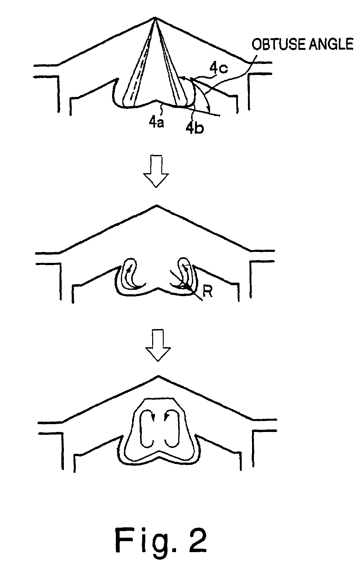
[0070]Referring now to FIGS. 17–19, a schematic view of a direct fuel injection engine invention will be described in accordance with a third embodiment of the present invention. This third embodiment is identical in construction and function as the second embodiment, except that a partial elliptically shaped piston C″ is formed in the piston in this third embodiment, instead of the circularly shaped cavity C′ of the second embodiment. Thus, the partial elliptically shaped piston C″ basically functions in the same manner as the circularly shaped cavity C′. Moreover, the general descriptions of the function of the circularly shaped cavity C′ also apply to the partial elliptically shaped piston C″. Thus, the shape of the cavity C″ causes the fuel streams injected from the fuel injection valve 11′ to form a fuel circulating region, as shown in FIG. 10. The fuel circulating region formed by the fuel streams injected from the fuel injection valve 11″ against the partial elliptically shap...


PUM


Abstract

A direct fuel injection engine has a fuel injection valve that injects fuel toward a cavity formed in a top of a piston, and a spark plug that ignites the fuel-air mixture resulting from the fuel injection. The direct fuel injection engine is configured to strengthen the penetration of the fuel streams, to improve the directionality of the fuel streams and to form in the cavity an agglomerate fuel-air mixture that is homogeneous and has uniform concentration. The cavity preferably has a bottom surface, a curved surface, and a flat surface. The fuel injection valve has a plurality of injection vents that spray solid-core fuel streams with angles formed between adjacent injection vents that are less than or equal to the spray angle of the fuel stream sprayed from each injection vent. The fuel streams form a combined fuel stream having a hollow circular cone shape.

Description

CROSS-REFERENCE TO RELATED APPLICATIONS[0001]This application is a divisional application of U.S. patent application Ser. No. 10 / 327,925 filed on Dec. 26, 2002 now U.S. Pat. No. 6,832,594, which claims priority to Japanese Patent Application No. JP2002-2453 filed on Jan. 9, 2002. The entire disclosures of U.S. patent application Ser. No. 10 / 327,925 and Japanese Patent Application No. JP2002-2453 are hereby incorporated herein by reference.BACKGROUND OF THE INVENTION[0002]1. Field of the Invention[0003]The present invention generally relates to a fuel injected internal combustion engine. More specifically, the present invention relates to a fuel injected internal combustion engine with direct fuel injection into the combustion chamber and spark-ignition.[0004]2. Background Information[0005]An example of a fuel injected internal combustion engine with direct fuel injection into the combustion chamber and spark-ignition is disclosed in Japanese Laid-Open Patent Publication No. 11-82028...

Claims


Application Information

Patent Timeline
Patent Type & Authority Patents(United States)
IPC IPC(8): F02B23/10F02F3/26F02B75/12
CPCF02B23/101F02B23/104F02F3/26F02B2023/103Y02T10/123Y02T10/125F02B2075/125Y02T10/12
Inventor HIRAYA, KOJIURUSHIHARA, TOMONORI
Owner NISSAN MOTOR CO LTD
Why Eureka
Try Eureka