
Dual area piston for transmission clutch and sequential control therefor

a transmission clutch and piston technology, applied in the direction of fluid actuated clutches, clutches, non-mechanical actuated clutches, etc., can solve problems affecting good shift quality, and achieve the effect of distinguishing static and dynamic clutch gains

Inactive Publication Date: 2006-09-12
FORD GLOBAL TECH LLC
View PDF13 Cites 31 Cited by
  • Summary
  • Abstract
  • Description
  • Claims
  • Application Information

AI Technical Summary

Benefits of technology

[0008]The invention relates to a single low / reverse clutch piston with two distinct areas, which create distinct static and dynamic clutch gains. This invention provides direct control of the pressurized state of the secondary piston area, the application and control of pressure in the clutch via an electronic control module and a pressure control device. This allows the dual area clutch design to be used for shift events in synchronous transmissions.
[0009]The clutch and control system of this invention produce very fast response times, low dynamic gain for excellent shift quality and high static capacity for high torque applications.
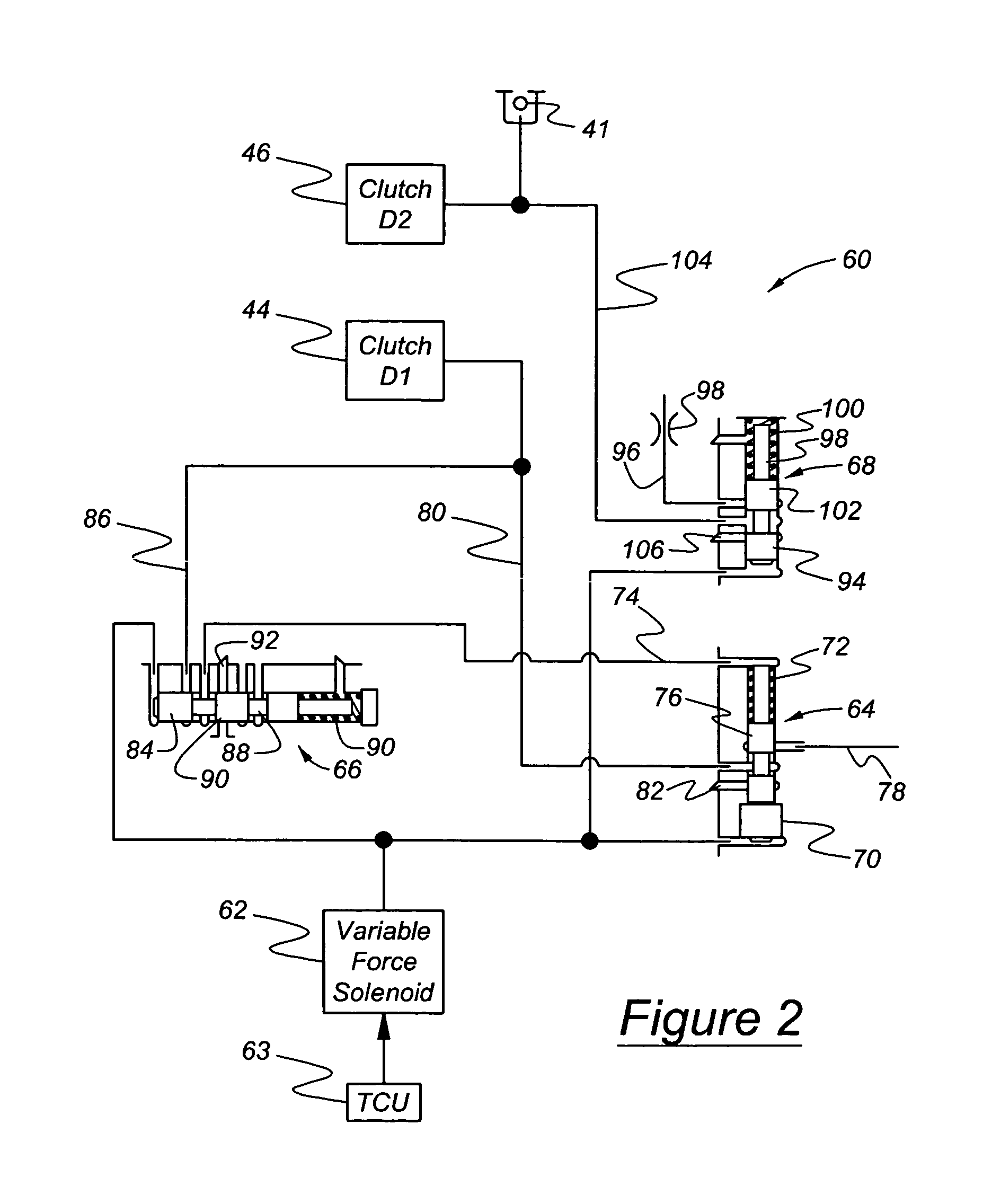
[0010]A control according to this invention uses dual valve trains to control application of each element and allows tuning of the response of each portion of the piston. The sequential nature of the operation of the clutch also reduces any excessive load on the hydraulic system of the transmission, thereby eliminating any capacity drops, and the resulting clutch slip, during application of pressure to the static area of the clutch piston.
[0011]The clutch design is combined with a control system that uses the smaller dynamic piston area to stroke the clutch and conduct the shift event. After the dynamic event is complete, the control system seats or closes a check ball located behind the secondary piston area and then pressurizes the secondary piston area to provide the added capacity required for static events. The clutch and control system use a single pressure control device and a valve train for each portion of the dual area piston to control activation of the clutch. The dynamic low gain portion of the piston has an optimized small volume to react quickly, a check ball to prevent creating a vacuum in the secondary piston volume when stroking the piston using the secondary area and to provide a low overall gain for excellent gearshift quality. The dynamic low gain portion of the piston has an optimized small volume to react quickly and provide a low overall gain for excellent gearshift quality. The secondary area is controlled via the same pressure control device as the first area, but uses its own valve train to determine when to apply. Once in static capacity mode with both piston areas applied, the clutch gain is high for static capacity purposes. The release of the clutch is also coordinated. The larger, static piston area is dumped quickly, while the shift event takes place on the smaller low gain portion of the piston.

Problems solved by technology

This high gain requirement, however, can affect good shift quality.

Method used


Image

  • Dual area piston for transmission clutch and sequential control therefor
  • Dual area piston for transmission clutch and sequential control therefor
  • Dual area piston for transmission clutch and sequential control therefor

Examples


Embodiment Construction

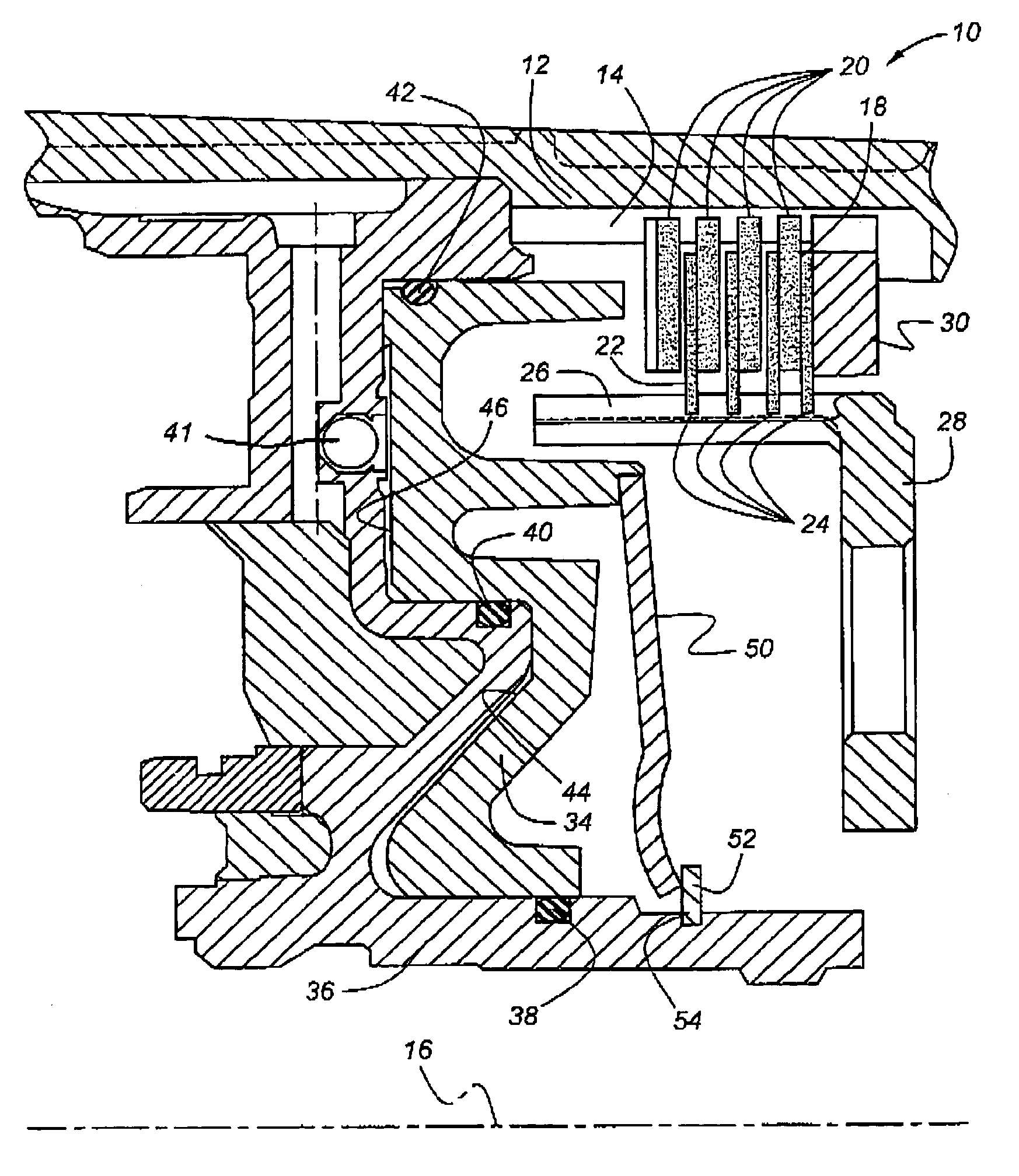
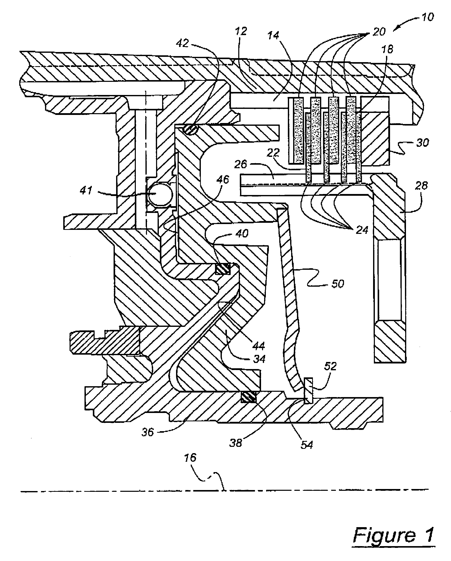
[0018]Referring now to the drawings, there is illustrated in FIG. 1 a hydraulically actuated friction clutch 10, preferably the low / reverse clutch of an automatic transmission, which is located in a transmission housing. A connecting member 12, secured to and rotating with a component of a planetary gear set, having an inner surface on which spline teeth 14, directed parallel to an axis 16, are formed. The clutch is arranged substantially symmetrically about axis 16. Pressure plates 18, spaced mutually along the axis 16, have teeth 20 located at a radially outer periphery and engaging the spline teeth 14. Located between each pressure plate 18 is a clutch disc 22 having teeth 24 located at a radially inner periphery and engaging axially directed spline teeth 26 formed on a member connecting 28, which is secured to and rotates with another component of a planetary gearset. A backing plate 30, similarly splined to the internal splines 14, is secure to the housing against displacement....


PUM


Abstract

A system for actuating a clutch that alternately driveably connects and disconnects components, includes a clutch having a piston that includes a first apply area and a second apply area, a fluid pressure source, a source of variable control pressure, and a control coupled with the fluid pressure source and operative in response to the control pressure to engage the clutch initially by increasing pressure steadily at the first apply area up to a first magnitude followed by a rapid increase in pressure at the first apply area and the second apply area above the first magnitude to a second magnitude.

Description

BACKGROUND OF THE INVENTION[0001]This invention relates to a friction control element, such as a hydraulically or pneumatically actuated clutch, of the type used to control operation of an automatic transmission. In particular, the invention pertains to a control for producing staged engagement and disengagement of such a clutch having at least two sealed areas on its actuating piston.[0002]Automatic transmissions are typically designed to transmit full engine torque and the engine torque as amplified by a torque converter at stall torque under static. i.e., non-shifting conditions. The control system of an automatic transmission includes a low / reverse clutch, which is applied or engaged to produce the lowest forward speed ratio and the reverse drive speed ratio. Such engagement produces a drive connection between components of the planetary gearing, which when selectively combined with the engagement of other control elements, results in the transmission operating in low gear or re...

Claims


Application Information

Patent Timeline
Patent Type & Authority Patents(United States)
IPC IPC(8): F16D25/0638F16D25/12
CPCF16D25/0638F16D48/02F16D2048/0212
Inventor BISHOP, BRIANBEZJAK, PETEJUNGBLUTH, KARL
Owner FORD GLOBAL TECH LLC
Learn More