Method and apparatus for sorting particles

a particle and particle technology, applied in mechanical equipment, laboratory glassware, membrane technology, etc., to achieve the effect of not eliminating the laminar flow

Inactive Publication Date: 2006-09-12
CYTONOMEST
View PDF25 Cites 66 Cited by
  • Summary
  • Abstract
  • Description
  • Claims
  • Application Information

AI Technical Summary

Benefits of technology

[0013]The present invention provides a method and apparatus for sorting particles moving through a closed channel system of capillary size. The particle sorting system of the invention provides a sorting module that can be assembled at low cost while providing an accurate means of sorting large amounts of particles per unit of time. The particle sorting system may include a plurality of closely coupled sorting modules which are combined to further increase the sorting rate. The particle sorting system may comprise a multi-stage sorting device for serially sorting streams of particles, in order to decrease the error rate.
[0026]According to a final aspect, a method of sorting small particles is provided. The method comprises the steps of providing a closed duct having an inlet and a fork at which the duct separates into two branch ducts, conducting a stream of liquid into the duct inlet with a stream of particles suspended therein, the particle stream normally flowing through a first one of the branch ducts surrounding the stream of liquid with a particle free enveloping current of liquid to produce substantially laminar flow and providing a measurement station along the closed duct upstream of the fork for sensing a predetermined property of particles in the stream and for producing a signal when the property is sensed. The method further comprises providing an actuator for applying a pressure on the liquid and providing means for buffering pressure variations in the liquid. The pressure buffering means cooperates with the pressure applying means to result in a momentary deflection of the liquid streaming through the duct substantially perpendicular to the normal direction of flow from the point where the pressure is applied towards the point where the pressure is buffered, causing the specific particle having the predetermined property to flow into the second branch duct without eliminating the laminar flow.

Problems solved by technology

When the external actuator is activated, the pressure in the reservoir of the activated bubble valve increases, deflecting the meniscus and causing a flow disturbance in the measurement duct to deflect the flow therein.

Method used


Image

  • Method and apparatus for sorting particles
  • Method and apparatus for sorting particles
  • Method and apparatus for sorting particles

Examples


Embodiment Construction

[0038]The present invention provides a particle sorting system for sorting particles suspended in a liquid. The particle sorting system provides high-throughput, low error sorting of particles based on a predetermined characteristic. The present invention will be described below relative to illustrative embodiments. Those skilled in the art will appreciate that the present invention may be implemented in a number of different applications and embodiments and is not specifically limited in its application to the particular embodiments depicted herein.

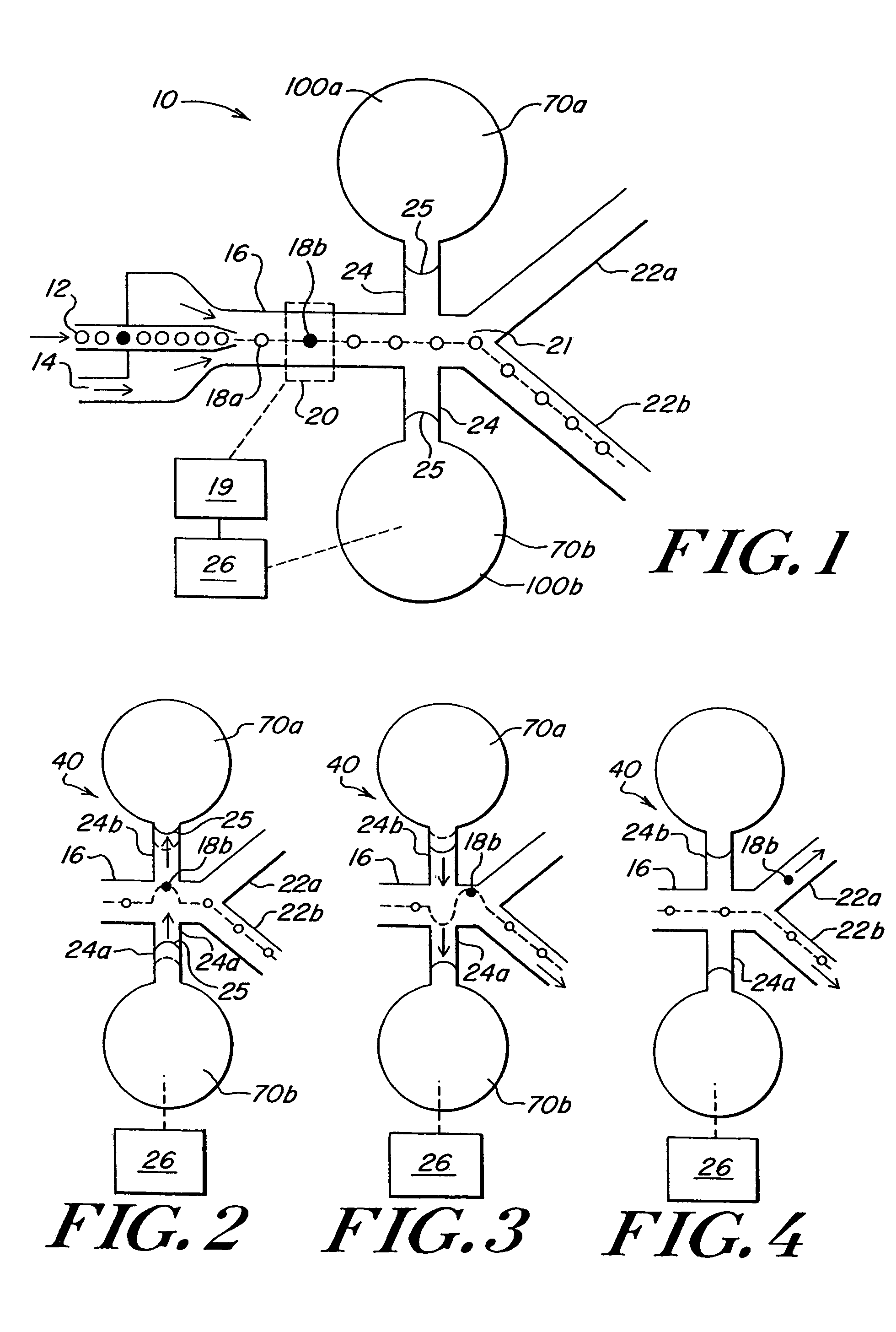
[0039]FIG. 1 shows a schematic of a particle sorting system according to an illustrative embodiment of the invention. According to one application of the present invention, a particle sorting system 10 comprises a closed channel system of capillary size for sorting particles. The channel system comprises a first supply duct 12 for introducing a stream of particles 18 and a second supply duct 14 for supplying a carrier liquid. The first s...


PUM

PropertyMeasurementUnit
angleaaaaaaaaaa
angleaaaaaaaaaa
angleaaaaaaaaaa

Abstract

A method and apparatus for sorting particles moving through a closed channel system of capillary size comprises a bubble valve for selectively generating a pressure pulse to separate a particle having a predetermined characteristic from a stream of particles. The particle sorting system may further include a buffer for absorbing the pressure pulse. The particle sorting system may include a plurality of closely coupled sorting modules which are combined to further increase the sorting rate. The particle sorting system may comprise a multi-stage sorting device for serially sorting streams of particles, in order to decrease the error rate.

Description

RELATED APPLICATIONS[0001]This application is a divisional of U.S. patent application Ser. No. 10 / 179,488, entitled “Method and Apparatus for Sorting Particles”, filed on Jun. 24, 2002 now U.S. Pat. No. 6,808,075, which claims priority to U.S. Provisional Patent Application No. 60 / 373,256 entitled “Microfluidic System Including a Bubble Valve for Regulating Fluid Flow Through a Microchannel” filed Apr. 17, 2002. The contents of both applications are herein incorporated by reference.FIELD OF THE INVENTION[0002]The invention relates to a method and apparatus for the sorting of particles in a suspension, where the input flow path of a sorting module can be split into several output channels. More particular, the invention relates to a particle sorting system in which a plurality of sorting modules are interconnected as to yield an increased particle throughput.BACKGROUND OF THE INVENTION[0003]In the fields of biotechnology, and especially cytology and drug screening, there is a need fo...

Claims


Application Information

Patent Timeline
Patent Type & Authority Patents(United States)
IPC IPC(8): B07C5/38B01L3/00B07C5/34F15C5/00F16K99/00G01N15/14
CPCB07C5/34F15C5/00F16K99/0001F16K99/0028F16K99/0046F16K99/0061G01N15/14B03B5/00F16K99/0048B01L3/5027Y10S209/932F16K2099/0084G01N2015/149Y10S209/906
Inventor BOHM, SEBASTIANGILBERT, JOHN R.DESHPANDE, MANISH
Owner CYTONOMEST
Why Eureka
Try Eureka