Ice detector for improved ice detection at near freezing condition

a technology of ice detector and near freezing condition, which is applied in the direction of variable measurement arrangement, instruments, transportation and packaging, etc., to achieve the effect of improving ice detection, and decreasing the temperature of the prob

Active Publication Date: 2006-09-12
ROSEMOUNT AEROSPACE
View PDF46 Cites 58 Cited by
  • Summary
  • Abstract
  • Description
  • Claims
  • Application Information

AI Technical Summary

Benefits of technology

[0007]An ice detector for providing a signal indicating ice formation includes a probe protruding into an airflow. The probe extends into the airflow from a strut. The strut has one or more features which allow the probe to accrete ice at a higher temperature than would conventionally be possible. Also, the probe can include surface roughness features that further improve ice detection. Surface roughness features on the probe include ice accreting edges at a distal end of the probe and features arranged on a side surface of the probe which cause the airflow to increase in turbulence, thereby decreasing the temperature of the probe. Decreasing the temperature of the probe, along with increasing the critical temperature of the probe, improves ice accretion on the probe, and thereby ice detection.

Problems solved by technology

Ensuring that the critical temperature of the ice detector probe is above the critical temperature of the wings or other control surfaces of an aircraft is a continuing challenge, particularly with newer airfoil designs.

Method used


Image

  • Ice detector for improved ice detection at near freezing condition
  • Ice detector for improved ice detection at near freezing condition
  • Ice detector for improved ice detection at near freezing condition

Examples


Embodiment Construction

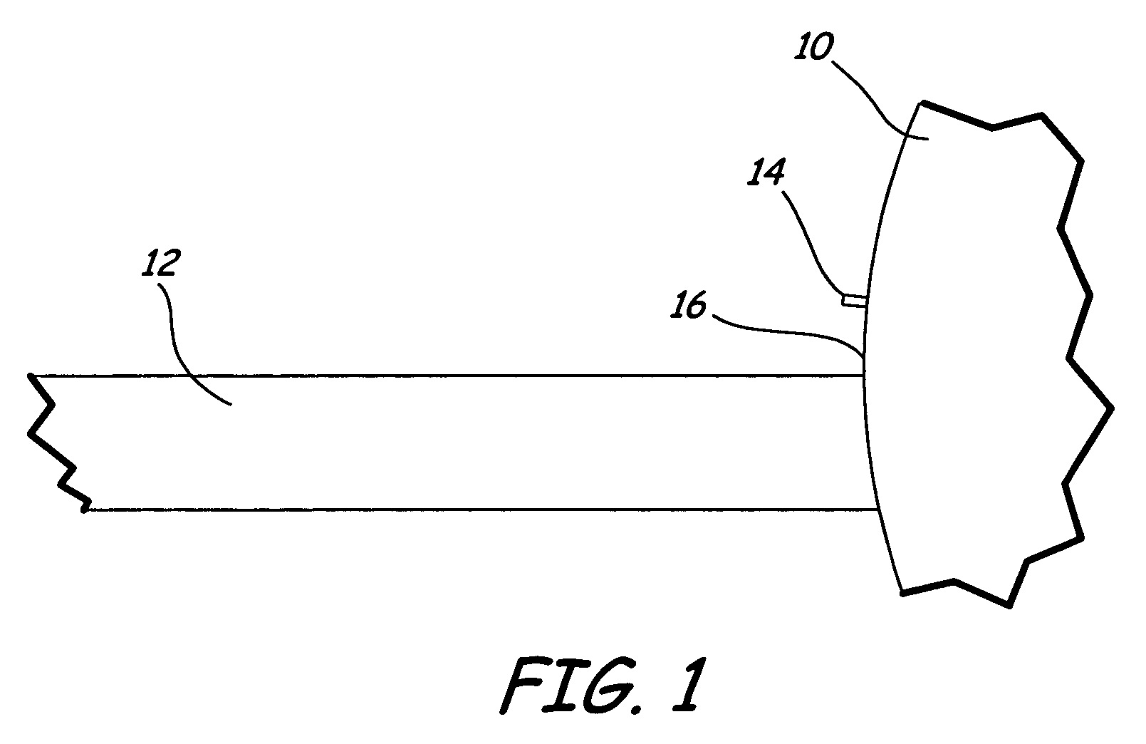
[0020]In FIG. 1, a typical aircraft indicated at 10 is of conventional design, and includes an airfoil cross-section shaped wing 12. An ice detector probe assembly 14 (ice detector 14), made according to the present invention, is supported on the skin or outer wall 16 of the aircraft. The ice detector 14 is positioned relative to the wing 12 at a known location that is selected to provide for detection of ice as air flows past the wing and the aircraft skin 16.

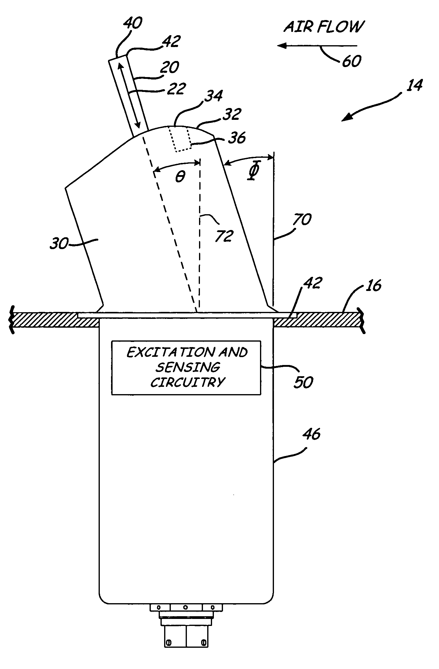
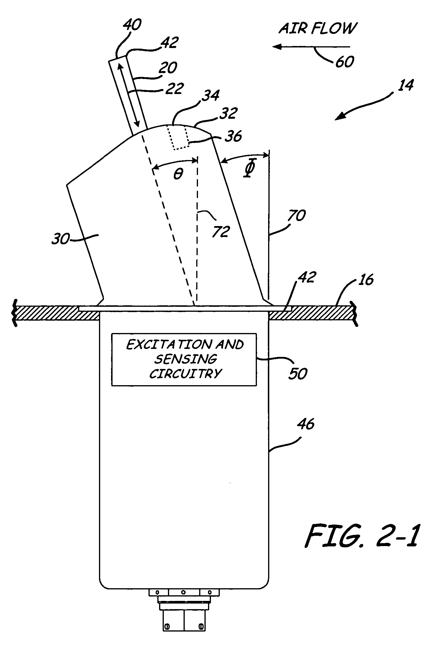
[0021]FIGS. 2-1 through 2-3 illustrate an embodiment of the ice detector 14 in accordance with the present invention. As shown, ice detector 14 includes a generally cylindrical probe 20 mounted onto a strut 30. Strut 30 is fixed to a mounting flange 42, which is supported by the aircraft skin 16 (not shown in FIGS. 2-2 and 2-3). A housing 46, typically located on the interior of the aircraft below skin 16, houses suitable excitation and sensing circuitry illustrated generally at 50, which is of conventional design.

[0022]As in ...


PUM


Abstract

An ice detector for providing a signal indicating ice formation includes a probe protruding into an airflow. The probe extends into the airflow from a strut. The strut has one or more features which allow the probe to accrete ice at a higher temperature than would conventionally be possible. Strut features can include a notch formed therein in an upwind direction relative to the probe, and a curved surface adjacent a point of extension of the probe from the strut.

Description

CROSS-REFERENCE TO RELATED APPLICATIONS[0001]Reference is hereby made to the following co-pending and commonly assigned patent application: U.S. application Ser. No. 10 / 814,384, filed Mar. 31, 2004, entitled “ICE DETECTOR FOR IMPROVED ICE DETECTION AT NEAR FREEZING CONDITION”, which is incorporated by reference in its entirety.BACKGROUND OF THE INVENTION[0002]The present invention relates to vibrating type ice detectors for use with aircraft and in any other locations where the detection of ice is of importance. More particularly, the present invention relates to ice detector configurations that increase the critical temperature limit of an ice detector probe to provide earlier ice detection.[0003]Existing ice detectors are useful in near freezing temperature conditions for detecting the formation of ice on the detector, and providing a warning of the ice formation prior to the formation of ice on the wings, engine nacelles, and other control surfaces of an aircraft. A frequently us...

Claims


Application Information

Patent Timeline
Patent Type & Authority Patents(United States)
IPC IPC(8): B64D15/20G08B19/02G08G1/09
CPCB64D15/20
Inventor OTTO, JOHN TIMOTHYFANSKA, JOSEPH MICHAELSCHRAM, KENNETH JAMESSEVERSON, JOHN ALBERTOWENS, DAVID GEORGECRONIN, DENNIS JAMES
Owner ROSEMOUNT AEROSPACE
Why Eureka
Try Eureka