
X-ray diagnosis apparatus having a common cooler

Inactive Publication Date: 2006-09-12
HITACHI MEDICAL CORP
View PDF16 Cites 15 Cited by
  • Summary
  • Abstract
  • Description
  • Claims
  • Application Information

AI Technical Summary

Benefits of technology

[0008]An object of the present invention is to enable a cooler of an X-ray generator and a cooler of a planer type X-ray detector to be used commonly to thereby reduce the number of necessary coolers.
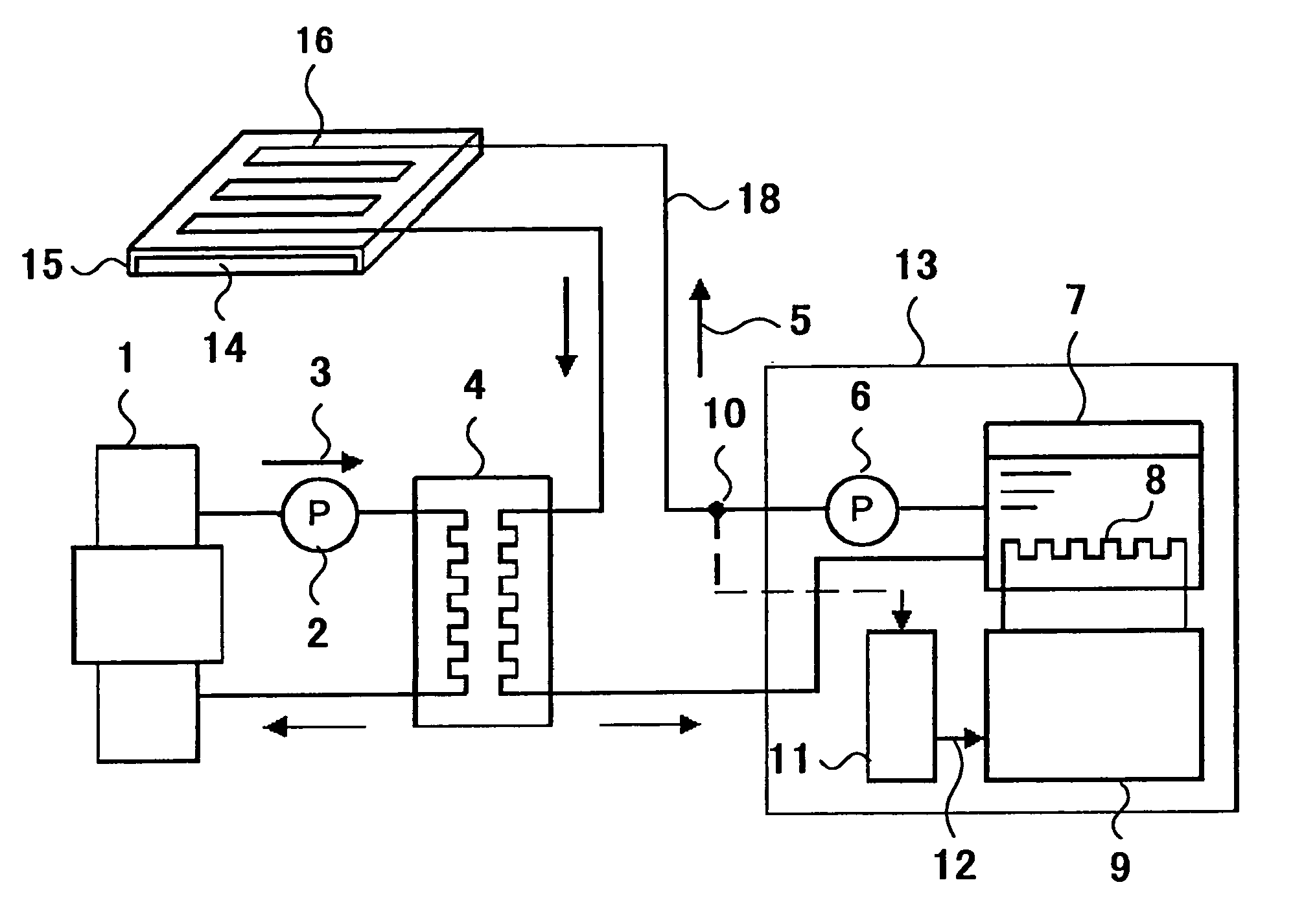
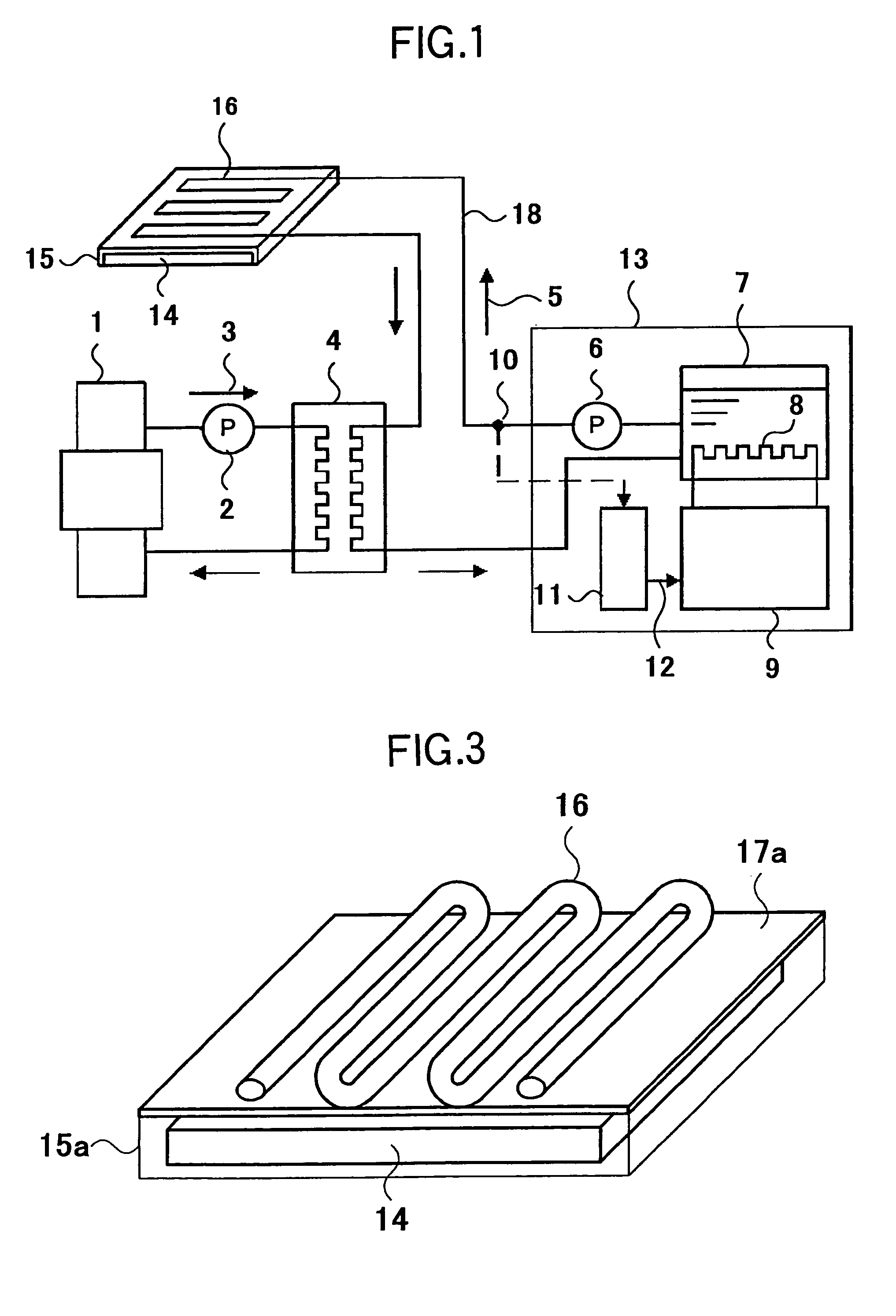
[0010]That is, the heat transfer medium, which is conventionally recycled only to the X-ray generator, is also recycled to the planer type X-ray detector so that the heat of both the X-ray generator and the planer type X-ray detector is transferred by the heat transfer medium, and the heat transfer medium is cooled by the shared cooling means to thereby cool the X-ray generator and the X-ray detector.
[0013]When water whose specific heat is large is used as the heat transfer medium of the present invention, the cooling efficiency of the heat transfer medium is improved and the heat transfer medium can be easily handled.
[0014]Further, it is preferable that the means for moving the heat transfer medium between the planer type X-ray detector and the cooling means be composed of a control means for detecting the temperature of the heat transfer medium flowing into the planer type X-ray detector and controlling the cooling means so that the detected temperature is kept within a set range. According to this arrangement, the operating temperature of the X-ray detector can be kept constant.
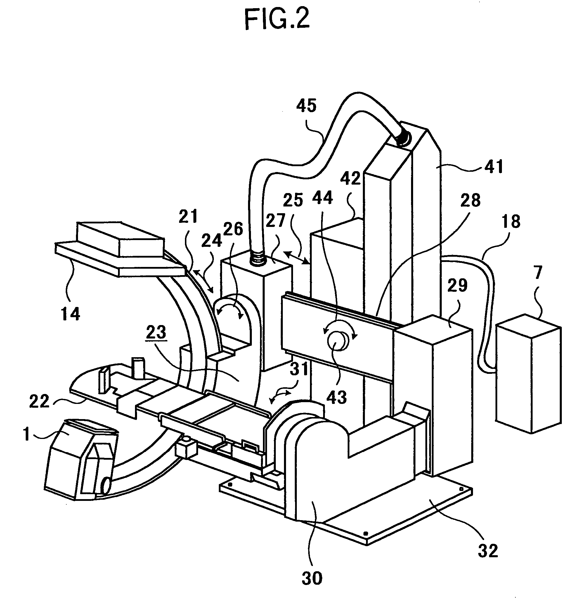
[0015]Here, the X-ray detector of the present invention may be arranged such that provides a plurality of X-ray detecting elements disposed two-dimensionally and flatly are hermetically sealed in a casing and a cooling tube, into which the heat transfer medium flows, is thermally connected to one of the surfaces of the casing on which the X-ray detecting elements are disposed. This arrangement is preferable because the cooling efficiency can be improved by directly cooling the X-ray detector. Further, a heat conductive plate may be attached to one of the surfaces of the casing, in which the plurality of X-ray detecting elements disposed two-dimensionally and flatly are hermetically sealed, and the cooling tube, in which the heat transfer medium flows, may be thermally attached to the heat conductive plate. According to this arrangement, the cooling efficiency can be improved because a heat absorbing area through which heat is absorbed from the casing is increased. Further, a plurality of X-ray detecting elements may be accommodated in a casing one of the surfaces of which opens, the open surface of the casing may be hermetically sealed by the heat conductive plate and the cooling tube, in which the heat transfer medium flows, may be thermally attached to the outside surface of the heat conductive plate. In any of the cases, it is preferable that a copper tube be used as the cooling tube and that the cooling tube be attached to the surface in a meandering shape.

Problems solved by technology

However, it is sufficient to keep the X-ray generator at a temperature equal to or less than 75° C. Further, although power consumption in fluoroscopy executed using the planer type X-ray detector is about 0.2 to 0.6 kw, power is consumed for a long time (for example, one hour).

Method used


Image

  • X-ray diagnosis apparatus having a common cooler
  • X-ray diagnosis apparatus having a common cooler
  • X-ray diagnosis apparatus having a common cooler

Examples


Embodiment Construction

[0021]An embodiment of the present invention will be explained below with reference to the accompanying drawings. FIG. 1 shows a system arrangement diagram of a cooling system that is a characteristic portion of an embodiment of the present invention, and FIG. 2 shows an outside view of an X-ray diagnosis apparatus of an embodiment to which the cooling system of FIG. 1 is applied.

[0022]As shown in FIG. 1, the cooling system of the embodiment of the present invention cools an X-ray tube device 1 and a planer type X-ray detector 14 by cooling water 5 acting as a heat transfer medium supplied from a single cooling device 13. The X-ray tube device 1 comprises an X-ray tube accommodated in a hermetically sealed vessel. Since a high voltage is applied to the X-ray tube of the X-ray tube device 1, high-voltage-resistant insulating oil 3 is used as the heat transfer medium. The X-ray tube device 1 is cooled by the insulating oil 3 circulating in the interior of the X-ray tube device 1. The ...


PUM


Abstract

An X-ray diagnosis apparatus is disclosed which includes two different cooling circuits and a single cooling portion. A first heat transfer medium is circulated for absorbing heat generated in the X-ray generator. A second heat transfer medium is circulated for absorbing the heat generated in the planer type X-ray detector. A heat exchanger is provided for exchanging heat between the first heat transfer medium and the second heat transfer medium. The cooling portion is coupled to the cooling circuit carrying the second heat transfer medium in order to cool the second heat transfer medium.

Description

TECHNICAL FIELD[0001]The present invention relates to an X-ray diagnosis apparatus or an X-ray examination apparatus (hereinafter, generically referred to as “X-ray diagnosis apparatus”), and more particularly, to a technical field of cooling an X-ray generator for generating X-rays and a planer type X-ray detector for detecting X-rays.BACKGROUND ART[0002]An X-ray diagnosis apparatus is used for diagnosis and the like of an object by taking an X-ray photograph of the object by irradiating X-rays generated from an X-ray generator to the object and exposing a film with X-rays having passed through the object. Further, the X-ray diagnosis apparatus is also used for diagnosis and the like by detecting X-rays having passed though the object using a planer type X-ray detector composed of a plurality of X-ray detecting elements disposed two-dimensionally and flatly, and by drawing an X-ray image having a distribution of intensity and density of the detected X-rays on a monitor in place of ...

Claims


Application Information

Patent Timeline
IPC IPC(8): H01J35/10G01T1/24H01J31/49A61B6/00A61B6/03
CPCA61B6/40A61B6/4488A61B6/4233A61B6/4441
Inventor OKAMURA, HIDEFUMIDOI, MOTOMICHI
Owner HITACHI MEDICAL CORP
Learn More