Method and apparatus for measuring transformer winding resistance

a transformer winding resistance and winding resistance technology, applied in the direction of resistance/reactance/impedence, measurement devices, instruments, etc., can solve the problems of exposing operators and equipment to hazards, complicated winding resistance measurement problems, and large and heavy devices, so as to minimize the risk to operators and equipment, the effect of significantly reducing the amount of stored energy

Inactive Publication Date: 2006-09-12
JAMES G BIDDLE
View PDF13 Cites 36 Cited by
  • Summary
  • Abstract
  • Description
  • Claims
  • Application Information

AI Technical Summary

Benefits of technology

[0018]The apparatus and method of the present invention achieves the minimization of inductive voltage drop L(i)di / dt by actively controlling di / dt such that the L(i)di / dt term is held very close to zero. This allows for the Ri voltage drop to dominate even when the controlled test current levels are substantially below the saturation values. Operating below the saturation current of a transformer allows for a compact, portable, device which can measure transformer winding resistances even for the largest power transformers in a few seconds, regardless of the magnetic and electric coupling between transformer windings. An additional benefit of making the measurements at substantially below saturation is that the amount of stored energy is significantly reduced, which in turn, minimizes the risk to the operators and the equipment.

Problems solved by technology

The presence of the ferromagnetic transformer core, which is a standard in the transformer art, further complicates the problem of winding resistance measurements by introduction of nonlinear dependence of the inductance on the transformer current and the magnetic properties of the ferromagnetic core material.
The high current testers of the prior art are large and heavy devices utilizing massive, heavily insulated conductors and connectors.
Operation in the vicinity of the saturation of the transformer core exposes the operators and the equipment to the hazards of accidental discharge of the significant magnetization energy stored in the transformer core.
In addition, the measurement process takes a relatively long time to bring the core near saturation to cause the L(i)di / dt voltage to be small enough to provide valid measurements by reducing L and di / dt to negligible levels.
A similarly long time must be spent to safely discharge and dissipate the stored energy.
Bridges are relatively common in transformer diagnostics prior art in spite of the inherent complexity of the method and complicated analysis and processing of the measurement results.

Method used


Image

  • Method and apparatus for measuring transformer winding resistance
  • Method and apparatus for measuring transformer winding resistance
  • Method and apparatus for measuring transformer winding resistance

Examples


first embodiment

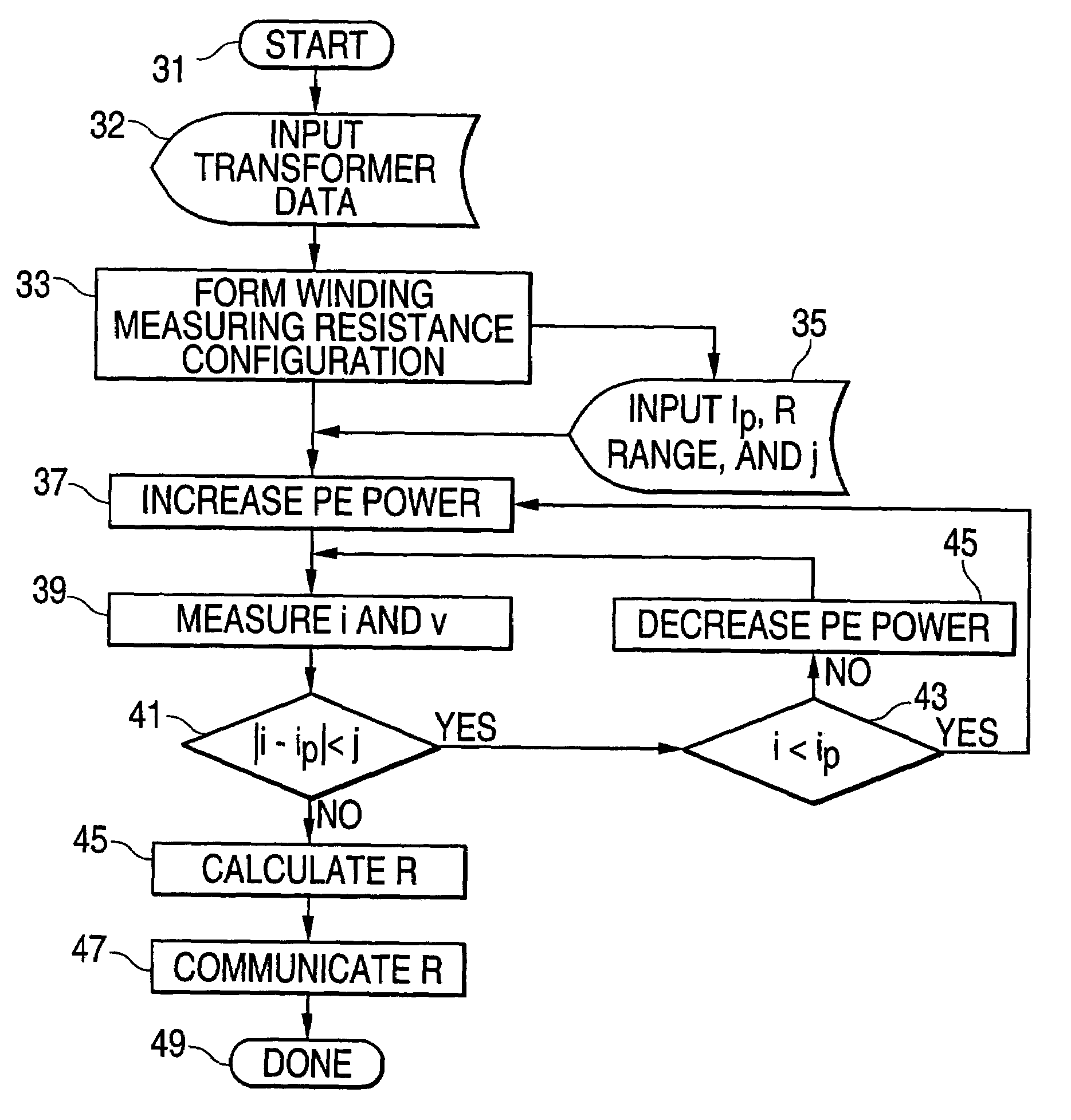
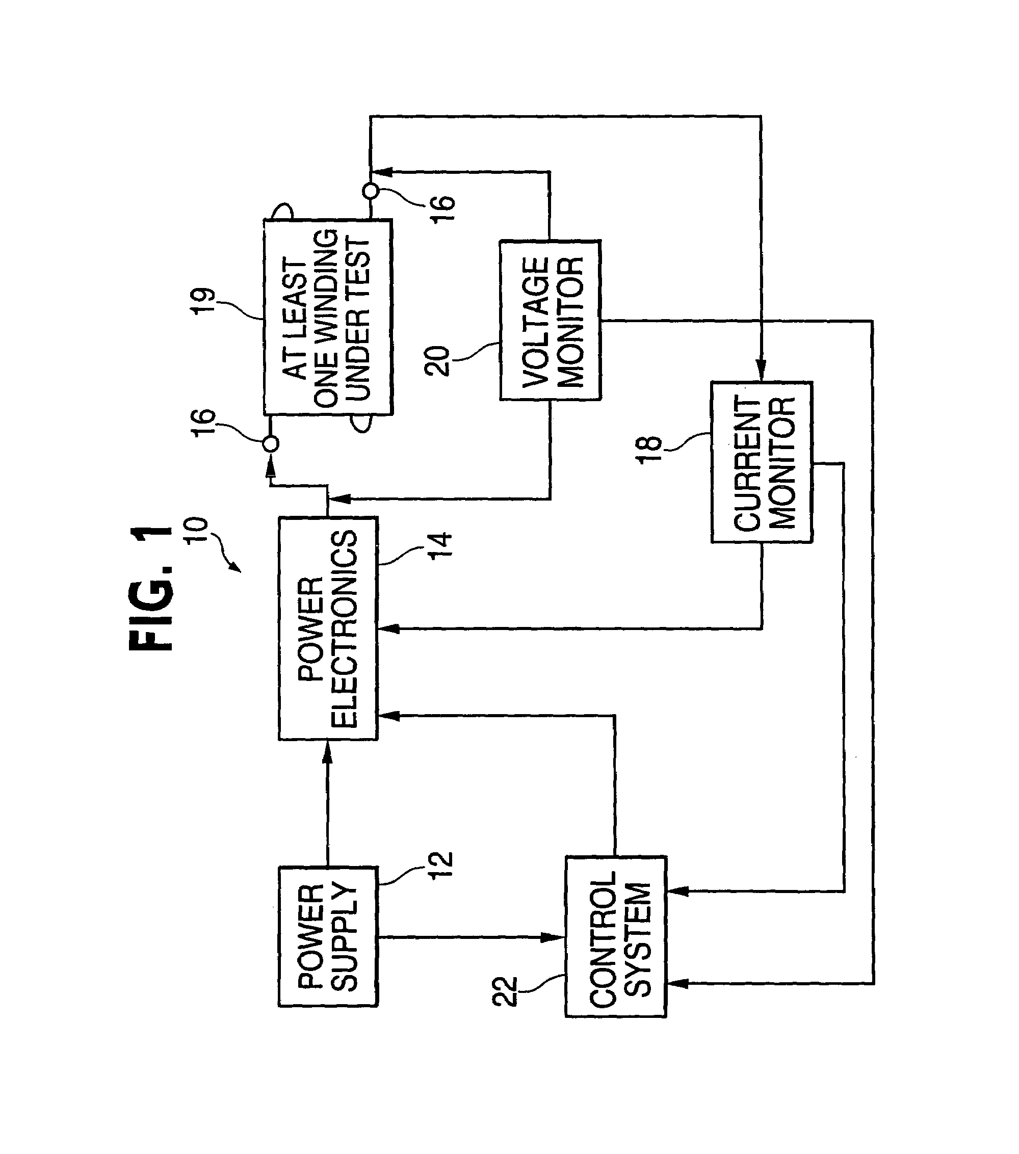
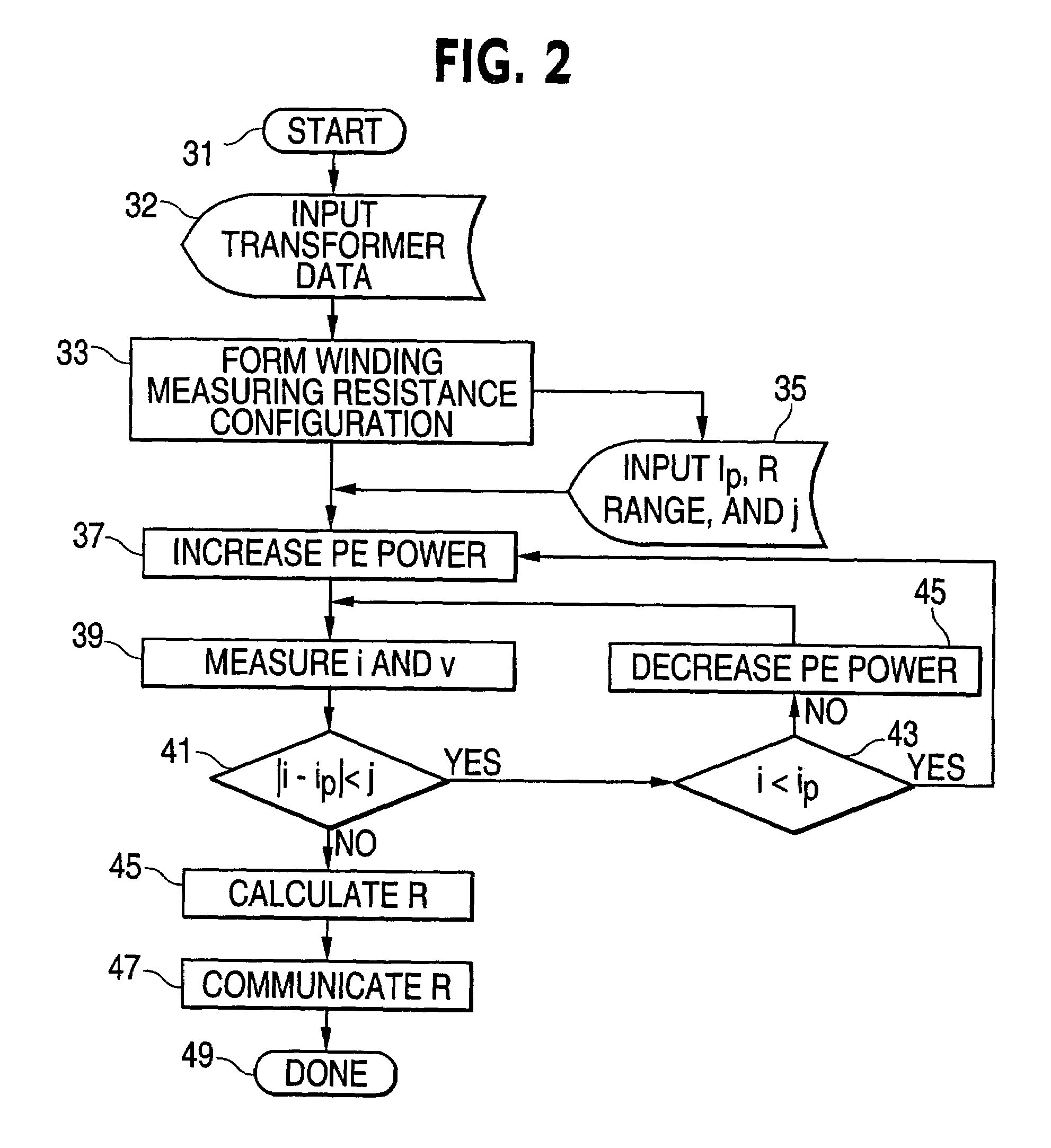
[0031]a transformer winding resistance measuring device 10 shown in FIG. 1 is powered by a power supply 12 which, when attached to an external source of electrical energy (not illustrated), provides electrical power to the components of the device. A controllable power electronics module 14 provides a desired test current signal with the maximum current substantially lower than the core saturation current to the connecting terminals 16 of the winding resistance measuring configuration 19 comprising at least one winding as for example illustrated in FIGS. 5a–d. A current monitor 18 measures the current flowing in the winding resistance measuring configuration as for example without limitation illustrated in FIGS. 5a–d during the testing, and a voltage monitor 20 that measures the voltage drop over the winding resistance measuring configuration 14. A control system 22 controls the controllable power module to generate the test current signal according to predetermined values, user inp...

embodiment 100

[0043]The preferred embodiment 100 is illustrated in FIG. 6. A regulated power supply 102 is coupled to a source of power source 103. The regulated power supply 102 provides a regulated DC output for transformer winding resistance testing. The power supply output voltage and current is regulated by the digital-to-analog converter (DAC) 104. The output of the DAC 104 is set by microprocessor 106. The test current control circuit 112 contains variable frequency and buck converters which, controlled by the microprocessor 106, deliver the appropriate amount of test current to the test current configuration circuit 114. The test current measuring circuit 108 measures the regulated power supply output current. The measured current is converted by analog-to-digital converter (ADC) 110 to its digital replica and transferred to a microprocessor 106. The test configuration circuit 114 utilizes a system of relays to conduct the test current through the appropriate connecting terminals 16 to th...


PUM


Abstract

The present invention is a method of and an apparatus for measuring resistances of at least one transformer winding (109) in configurations of connected transformers windings. The method is based on increasing driving power from the source of electrical energy (12, 102) until the current reaches a predetermined level, which is below the core saturation current level of the measured transformer or the measuring device current limit, and then controls the power of the source of the electrical energy to maintain predetermined current flowing through the at least one winding over a time period sufficient to cause a L di/dt contribution to a voltage drop across the at least one winding to decrease below a threshold level. The apparatus measures simultaneously the constant current flowing in the at least one winding and the voltage drop over the at least one winding after the predetermined time period has elapsed. The resistance of the at least one winding is calculated from the voltage drop over the at least one winding and the current flowing in the at least one winding.

Description

BACKGROUND[0001]1. Field of the Invention[0002]The present invention pertains to the method and devices designed and constructed to test transformers. In particular, the present invention describes a method and apparatus for testing resistances of transformer windings and configurations of connected transformers windings. The invention has a broad applicability for testing of transformers of different sizes and power ratings.[0003]2. Description of the Prior Art[0004]Measurements of transformer winding resistances are common transformer diagnostic techniques. It is used to detect variety of transformer failures related to damage of winding conductors, terminals, or insulation.[0005]Measurement of transformer winding resistance is inherently non-trivial because of the high inductance required for the basic function of the transformer. Some power transformers may exhibit inductances in excess of 2000H. Voltage drops over transformer windings are usually dominated by the inductive L(i)...

Claims


Application Information

Patent Timeline
Patent Type & Authority Patents(United States)
IPC IPC(8): G01R29/22
CPCG01R31/027G01R27/02G01R31/62
Inventor FRANK, JERRYGILMAN, EUGENE
Owner JAMES G BIDDLE
Why Eureka
Try Eureka