Single-frequency narrow linewidth 2 μm fiber laser

a fiber laser and narrow linewidth technology, applied in the field of single-frequency 2 m fiber lasers, can solve the problems of limited single-transverse mode performance of current 2 m fiber laser technology, and achieve the effects of reducing noise, facilitating splicing, and stable single-frequency operation

Inactive Publication Date: 2006-09-12
NP PHOTONICS A CORP OF DELAWARE
View PDF27 Cites 31 Cited by
  • Summary
  • Abstract
  • Description
  • Claims
  • Application Information

AI Technical Summary

Benefits of technology

[0012]The 2 μm fiber laser includes a gain fiber formed of a low phonon energy glass host, either fluoride based or an oxide-based multi-component glass such as germanate or tellurite, that is doped with triply ionized rare-earth thulium or holmium oxide or mixtures thereof. Erbium and ytterbium may be used to absorb and transfer pump energy to the active ions. Fiber gratings are formed in sections of passive silica fiber and fused to the gain fiber to form the resonant cavity. A doping concentration of 0.5 to 15 wt. % for either thulium or holmium oxides or mixtures thereof produces adequate gain, hence output power levels for fiber lengths less than 5 cm and preferably less than 3 cm to enable stable single-frequency operation. Formation of the gratings in passive silica fiber both facilitates splicing to other optical components and reduces noise thus improving linewidth. The pump can be a multimode or single mode laser. In the case of a single mode laser, the use of a polarization maintaining (PM) fiber in the pump source further improves wavelength stability, linewidth and vibration / acoustic sensitivity.
[0013]In another embodiment, the gain fiber is a polarization maintaining (PM) fiber, which reduces the noise level in the laser and improves output power stability. As a result of their specific local environment, the active ions experience an anisotropy that leads to polarization dependent gain, which means that the gain spectra for two different polarization components are not the same. Combining polarization selective feedback with a polarization maintaining active fiber reduces the low frequency noise that results from random polarization fluctuations inside the laser cavity.

Problems solved by technology

Current 2 μm fiber laser technology is limited to single transverse mode performance.

Method used


Image

  • Single-frequency narrow linewidth 2 μm fiber laser
  • Single-frequency narrow linewidth 2 μm fiber laser
  • Single-frequency narrow linewidth 2 μm fiber laser

Examples


Embodiment Construction

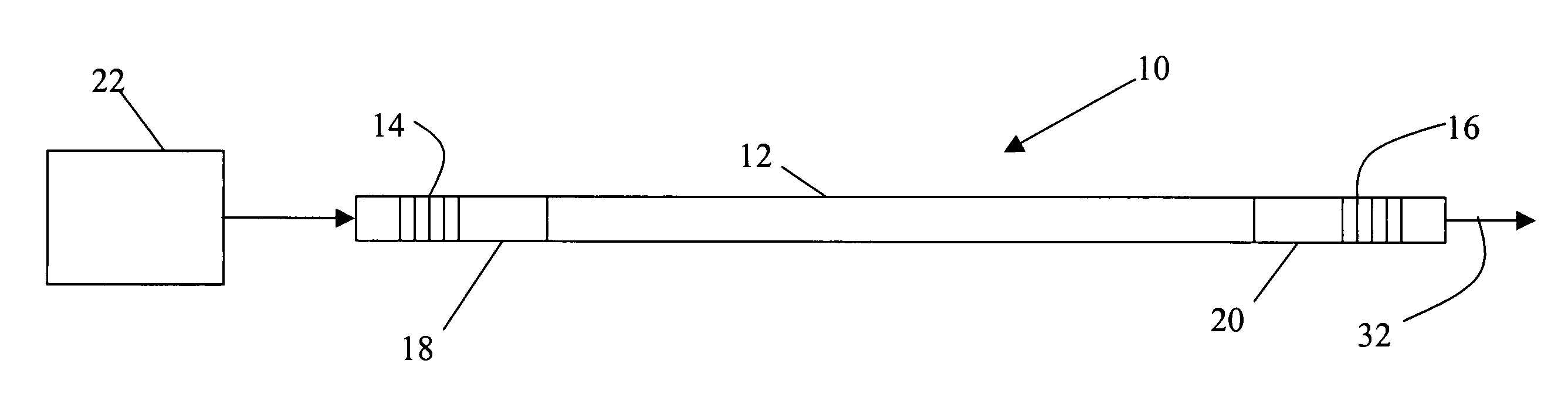
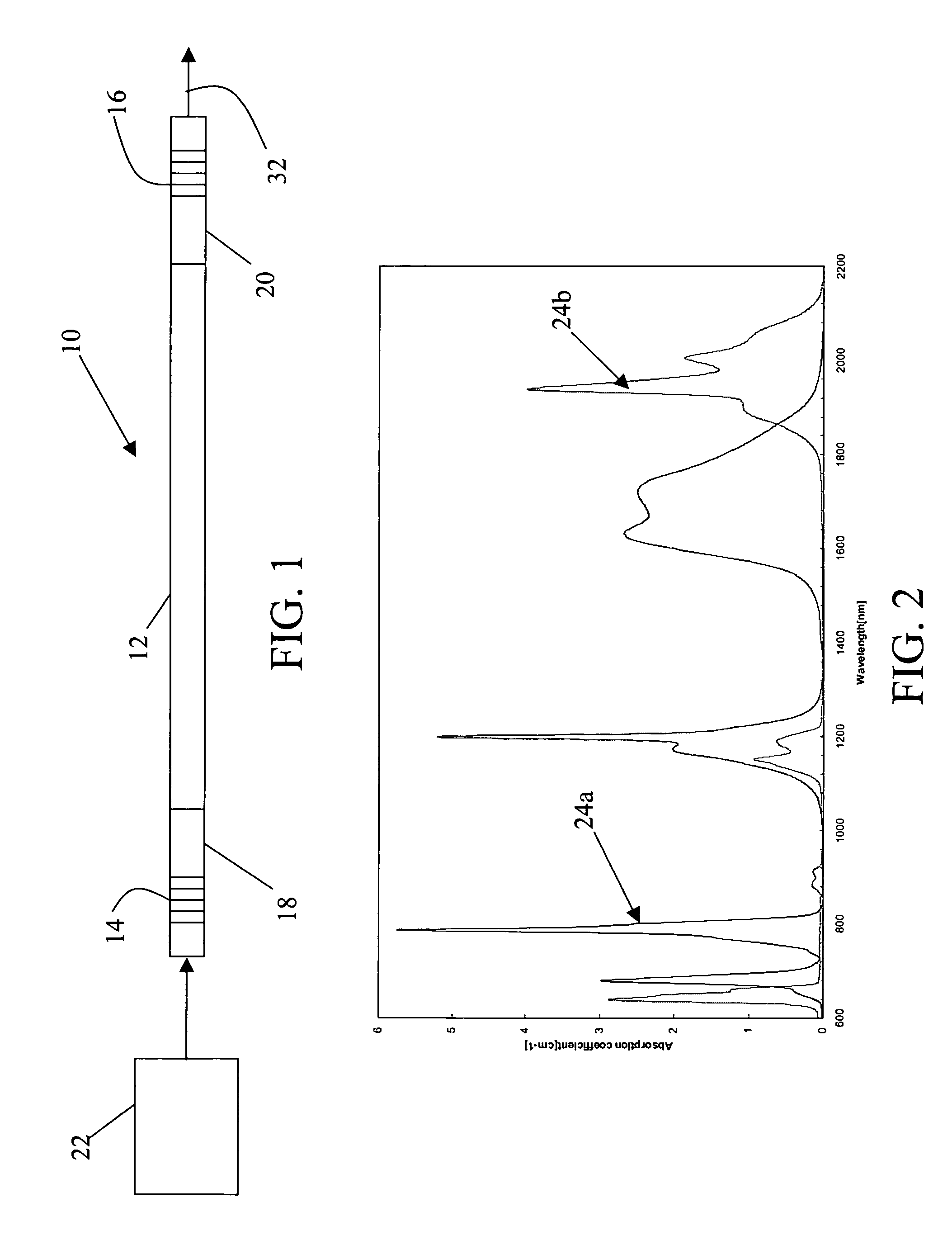
[0021]The present invention provides a compact single frequency, single-mode 2 μm fiber laser with narrow linewidth, less than 100 kHz and preferably less than 10 kHz. As shown in FIGS. 1 through 4, a 2 μm fiber laser 10 includes a single mode gain fiber 12 formed of a low phonon energy glass host doped with triply ionized rare-earth thulmium or holmium oxide or mixtures thereof. Erbium or ytterbium dopants may also be used to absorb and then transfer pump energy to the active ions. The low phonon energy glass host is selected from either an oxide-based multi-component germanate or tellurite glasses or a fluoride based glass. These host glasses have sufficiently low phonon energy to slow down the multi-phonon relaxation process. Narrowband and broadband fiber gratings 14 and 16, respectively, are formed in sections of passive silica fiber 18 and 20 and fused to the ends of gain fiber 12 to form a resonant cavity that provides the feedback necessary to sustain laser operation. The re...


PUM

PropertyMeasurementUnit
lengthaaaaaaaaaa
center wavelengthaaaaaaaaaa
lengthaaaaaaaaaa

Abstract

A compact single frequency, single-mode 2 μm fiber laser with narrow linewidth, <100 kHz and preferably <100 kHz, is formed with a low phonon energy glass doped with triply ionized rare-earth thulium and / or holmium oxide and fiber gratings formed in sections of passive silica fiber and fused thereto. Formation of the gratings in passive silica fiber both facilitates splicing to other optical components and reduces noise thus improving linewidth. An increased doping concentration of 0.5 to 15 wt. % for thulium, holmium or mixtures thereof produces adequate gain, hence output power levels for fiber lengths less than 5 cm and preferably less than 3 cm to enable single-frequency operation.

Description

CROSS-REFERENCE TO RELATED APPLICATIONS[0001]This application claims benefit of priority under 35 U.S.C. 120 to and is a continuation in part of U.S. application Ser. No. 10 / 056,830 entitled “Rare-Earth Doped Phosphate-Glass Single-Mode Fiber Lasers” filed on Jan. 24, 2002, now U.S. Pat. No. 6,816,514, the entire contents of which are incorporated by reference.GOVERNMENTAL RIGHTS[0002]This invention was made with Government support under Contract NNL05AA94P awarded by NASA. The government has certain rights in this invention.BACKGROUND OF THE INVENTION[0003]1. Field of the Invention[0004]This invention relates to fiber lasers and more specifically to a single frequency 2 μm fiber laser with narrow linewidth (<100 kHz and preferably <10 kHz) formed from glass fibers doped with Thulium and Holmium oxides and mixtures thereof.[0005]2. Description of the Related Art[0006]Rare-earth doped glass fiber lasers were first proposed in the 1960s and have received considerable attention i...

Claims


Application Information

Patent Timeline
Patent Type & Authority Patents(United States)
IPC IPC(8): H01S3/30H01S3/067H01S3/094H01S3/16
CPCH01S3/06716H01S3/0675H01S3/094003H01S3/1655H01S3/1618H01S3/163H01S3/1608
Inventor JIANG, SHIBINSPIEGELBERG, CHRISTINELUO, TAO
Owner NP PHOTONICS A CORP OF DELAWARE
Why Eureka
Try Eureka