
Composite Single-Mode/Multimode Optical Fiber

a single-mode/multi-mode, optical fiber technology, applied in the field of optical fibers, can solve the problems of optical fiber failure, extremely limited success, and tended to fail in wells, and achieve the effects of increasing or decreasing the photosensitivity of said entities, and increasing the ease with which an optical grating is operated

Pending Publication Date: 2021-11-25
FIBERCORE INC
View PDF10 Cites 0 Cited by
  • Summary
  • Abstract
  • Description
  • Claims
  • Application Information

AI Technical Summary

Benefits of technology

The patent text describes a new technology that uses concentric cores to improve the connection and splicing of fibers in cables. This is useful in situations where the connections need to be remote or difficult to perform, such as in oil / gas wells or subsea. By using multiple fibers with concentric cores, the technology ensures that all the fibers are aligned simultaneously, which reduces errors and ensures accurate measurement of the same environment. This technology also minimizes errors and improves the accuracy of the measurements.

Problems solved by technology

In the early days of optical sensing in oil and gas wells, optical fiber was not specifically designed for its intended purpose and tended to fail in wells after only a short amount of time, often due to degradation of coatings on the fiber, or hydrogen-induced darkening of the fiber.
Some work has been attempted in this area but success has been extremely limited.
As these came into the market, and as enhanced oil recovery methods such as acid injection became more prevalent, it was found that in some combination of temperature and acid concentration that the welded seam along the outer metal tube would corrode quite rapidly due to the high levels of stress in the metal—this type of corrosion is called stress corrosion cracking and leads to degradation in the quality and usefulness of the cable.
However, due to the nature of the construction of such pre-built cables, for which outer metal tubes are welded and either drawn or roll reduced, it is not possible to have an annealed outer metal tube.
The downside of this methodology is that only one, or perhaps in some cases two fibers can be pumped successfully into the well.
This limits the amount of sensing that can be performed, and to some extent also limits the potential accuracy of the sensing.
Pumped fiber applications can tend to expose a fiber to over 180° C. oil and gas wells and so this can limit the use of fibers that suffer compromised operability at these temperatures; and2) using a pre-built cable.
The disadvantages of this option include that it is not possible to replace the fibers without a costly well workover of the well completion.
It also implies that optical fiber connections may be needed during installation that may be costly or not possible depending on the type of well completion used.
Also, in making the cable, the outer metal tube of the cable is often work-hardened, which often creates handling issues—due to the increased stiffness—and also can increase the chances of corrosion in a high temperature, caustic well.
This approach can, however, suffer difficulties caused by restricted space.
Some deployment methods, such as pumping the fibers into tubes, may also be impractical with multiple fibers as discussed above.
Another issue is that the fibers are separated, which may affect the quality of a measurement system.
This can be seen, for example, if a temperature measurement of one fiber is used to compensate or correct the measurement of another fiber—a temperature difference between the two fibers may cause an error.
Also, the limitation on the number of ports on parts of the well completions, such as well heads, tubing hangers and packers (as known in the art), may impose a limitation on the number of fibers used.

Method used


Image

  • Composite Single-Mode/Multimode Optical Fiber
  • Composite Single-Mode/Multimode Optical Fiber
  • Composite Single-Mode/Multimode Optical Fiber

Examples


Embodiment Construction

[0089]Specific embodiments will now be described by way of example only, and with reference to the accompanying drawings, in which:

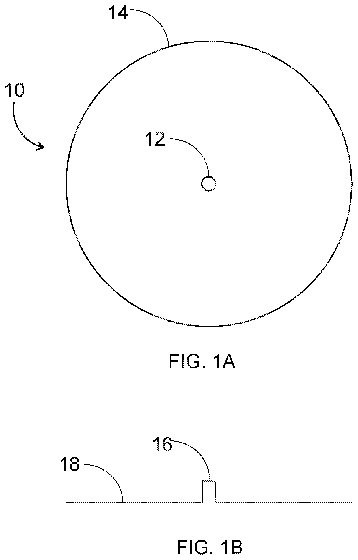
[0090]FIG. 1A shows a sectional view of a single mode optical fiber in accordance with currently available technology;

[0091]FIG. 1B shows a refractive index profile of the single mode fiber of FIG. 1A;

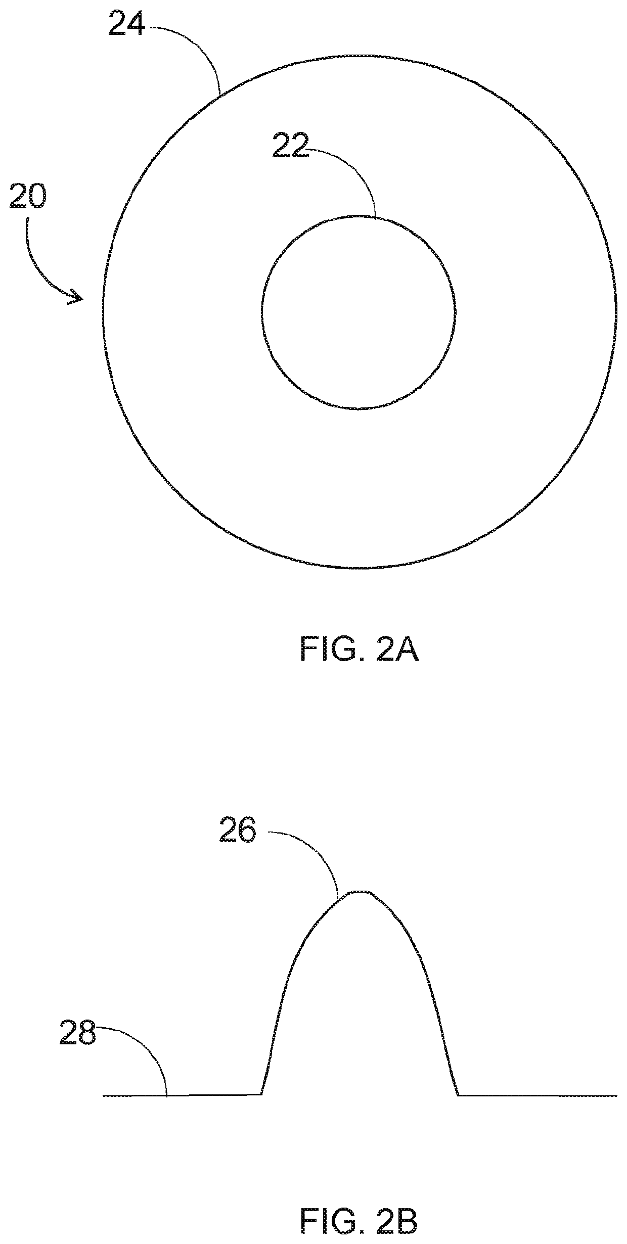
[0092]FIG. 2A shows a sectional view of a multimode optical fiber in accordance with currently available technology;

[0093]FIG. 2B shows a refractive index profile of the multimode fiber of FIG. 2A;

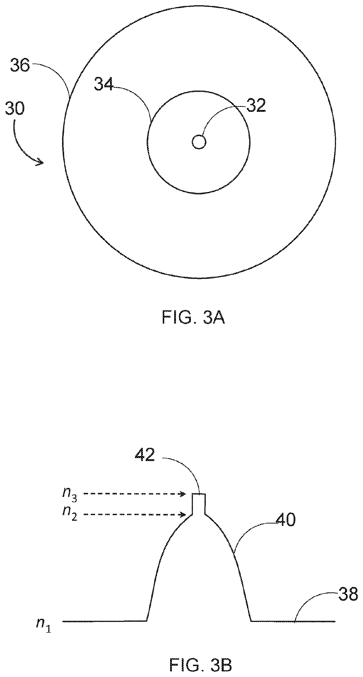
[0094]FIG. 3A shows a sectional view of an example embodiment of an optical fiber according to the first aspect of the present invention;

[0095]FIG. 3B shows a refractive index profile of the optical fiber of FIG. 3A;

[0096]FIG. 4A shows a sectional view of an additional example embodiment of an optical fiber according to the first aspect of the present invention;

[0097]FIG. 4B shows a refractive index profile of the optical fiber of FIG. 4A;

[0098]FIG. 5 shows a sect...


PUM

PropertyMeasurementUnit
diameteraaaaaaaaaa
diameteraaaaaaaaaa
temperaturesaaaaaaaaaa

Abstract

A composite optical fiber is provided for permitting sensing of multiple parameters. The optical fiber is for incorporation into a sensing system, the optical fiber comprising: a single mode optical fiber core, a multimode optical fiber core, and an optical fiber cladding layer surrounding the single mode optical fiber core and the multimode optical fiber core. The optical fiber provided preferably enables multiple sensing and / or measurements to take place at a single location and at a single time.

Description

FIELD OF THE INVENTION[0001]The present invention relates to optical fibers, in particular to multicore optical fibers for use in multiple sensing applications including optical sensing.BACKGROUND TO THE INVENTION[0002]In the early days of optical sensing in oil and gas wells, optical fiber was not specifically designed for its intended purpose and tended to fail in wells after only a short amount of time, often due to degradation of coatings on the fiber, or hydrogen-induced darkening of the fiber.[0003]As a result of this, some companies used a technique to pump a fiber into an empty annealed control line that ran from the well head to the toe of the well. When the fiber failed, they could then pump out the bad fiber and install another fiber.[0004]This worked to some extent in the early days of use of optical fibers in well applications, as the key parameter to measure was mainly temperature. As a result of the few desired sensing parameters, there was not much interest in insert...

Claims


Application Information

Patent Timeline
Patent Type & Authority Applications(United States)
IPC IPC(8): G01D5/353G02B6/02G01H9/00G01K11/32E21B47/07
CPCG01D5/3538G02B6/02042G02B6/0285G01K11/32E21B47/07G01H9/004G02B6/0283G02B6/036E21B17/206E21B47/113E21B47/135E21B47/114G01D5/26G01D5/268
Inventor RAMOS, ROGERIO TADEU
Owner FIBERCORE INC
Learn More