
Device and method for splicing array optical fiber with large-size quartz end cap

a technology of array optical fiber and quartz end cap, which is applied in the field of splicing array optical fiber with quartz end cap, can solve the problems of inability to reduce the interval between adjacent optical fibers, the theoretical limit of the output power of single-channel single-mode fiber lasers, and the inability to synthesize ligh

Pending Publication Date: 2022-07-07
SHANGHAI INST OF OPTICS & FINE MECHANICS CHINESE ACAD OF SCI
View PDF0 Cites 0 Cited by
  • Summary
  • Abstract
  • Description
  • Claims
  • Application Information

AI Technical Summary

Benefits of technology

The present invention relates to a splicing method for array fibers in a high-brightness spectrum synthetic system. The technical effects of this invention include: 1) improved splicing quality by using a double-beam coupling uniform heating technology to release welding stress and facilitate splicing of the array fiber end cap; 2) realization of a uniform temperature field in the splicing area through heating by two parallel strip-shaped light spots, which facilitates splicing of adjacent fibers with different sizes and increases the size of the laser array compared to using multiple fiber end caps in a linear array; and 3) providing an optimal design reference for the laser array part in the high-brightness spectrum synthetic system.

Problems solved by technology

There is a theoretical limit for the output power of single-channel single-mode fiber lasers, given the limitations of nonlinear effect, mode instability effect, material damage characteristics, etc.
However, in the practical synthetic system, the beam quality of the synthesized light is worse than that of the single fiber input laser.
As the single-path optical fiber output head needs to be mechanically clamped and water-cooled in a spectral beam combining device, the interval between adjacent optical fibers cannot be reduced without limitation such that the spectral beam combining device cannot be compact and lightweight, thereby limiting the application of the high-brightness optical fiber laser on a mobile platform.

Method used


Image

  • Device and method for splicing array optical fiber with large-size quartz end cap
  • Device and method for splicing array optical fiber with large-size quartz end cap
  • Device and method for splicing array optical fiber with large-size quartz end cap

Examples


Embodiment Construction

[0037]The present invention is further explained in the following detailed embodiments with reference to the accompanying drawings. In the following description, many specific details are set forth in order to provide a thorough understanding of the present invention. However, the present invention can be implemented in many other ways different from those described herein, and those skilled in the art can make similar improvements without departing from the connotation of the present invention. Therefore, the present invention is not limited by the specific implementation disclosed below.

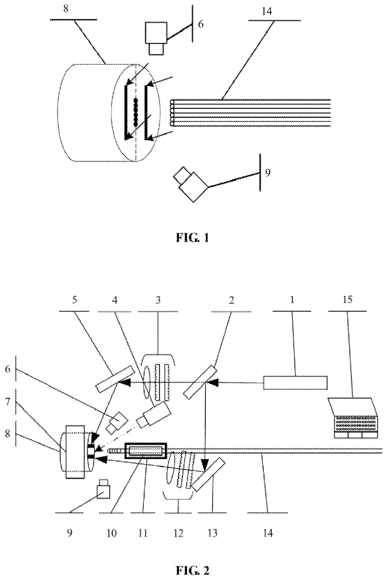
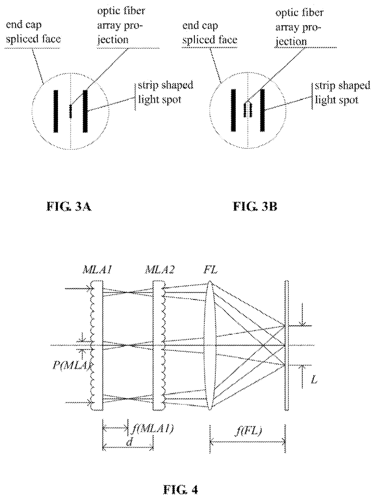
[0038]The device for realizing the splicing of the array fiber and the large-size quartz end cap according to one embodiment of the present invention is shown in FIGS. 1 to 3B. The device for realizing the splicing of the array fiber and the large-size quartz end cap according to the embodiment of the present invention comprises a carbon dioxide laser 1, a beam splitter 2, a first beam shaper 3, a ...


PUM


Abstract

A device for realizing the splicing of an array fiber and a large-size quartz end cap comprises a carbon dioxide laser, a light splitter, a light beam shaper, a high reflectivity mirror, an image detection module, an array fiber and a carrier thereof, a large-size quartz end cap and a carrier thereof, a stepping motor, a thermodetector, and a computer; a laser beam emitted by the carbon dioxide laser is divided into two light beams through a light splitter, after the two light beams respectively pass through the beam shaper and the high reflectivity mirror, two strip-shaped light spots with uniform power density are integrally formed to heat a splicing face of the large-size quartz end cap, a uniform temperature field of a target splicing area is achieved through indirect heating and heat conduction.

Description

CROSS-REFERENCE TO RELATED APPLICATIONS[0001]The subject application claims priority to Chinese Patent Application No. 202110001757.2 filed on Jan. 4, 2021, in China. The Chinese priority application is incorporated herein by reference.TECHNICAL FIELD[0002]The present invention relates to the field of splicing optical fiber end cap, and particularly, device and method for splicing an array optical fiber with a large-size quartz end cap.BACKGROUND ART[0003]The high-brightness fiber laser has wide application in industry, medical treatment, national defense, etc. There is a theoretical limit for the output power of single-channel single-mode fiber lasers, given the limitations of nonlinear effect, mode instability effect, material damage characteristics, etc. Spectral beam combining is an important technical way to achieve high power and high beam quality laser output. With a specific beam combining method, the output laser power is improved, and the output laser is guaranteed to have...

Claims


Application Information

Patent Timeline
IPC IPC(8): G02B6/255
CPCG02B6/2553G02B6/2555G02B6/2551G02B6/2808G02B6/3672
Inventor ZHANG, HAIBOWU, MENGHAOHE, BINGLEI, YUZHOU, JUNQI, YUNFENGYUAN, ZHIJUNYE, REN
Owner SHANGHAI INST OF OPTICS & FINE MECHANICS CHINESE ACAD OF SCI
Learn More