Dual boundary pressure zone three dimensional microphone and hearing aid

a three-dimensional microphone and a pressure zone technology, applied in the field of acoustics, can solve the problems of phase problems, potential feedback in the system, pre-eminence and proximity effects, etc., and achieve the effects of reducing or eliminating proximity and pre-eminence effects, good high frequency response, and good high frequency respons

Inactive Publication Date: 2006-09-12
KING JAMES T
View PDF7 Cites 0 Cited by
  • Summary
  • Abstract
  • Description
  • Claims
  • Application Information

AI Technical Summary

Benefits of technology

[0036]Another advantage of the invention is that the boundary button present on the hearing aid creates a 6 dB boost in gain.
[0037]Another advantage of the invention is that a good high frequency response is attained which is advantageous to most users with hearing loss, which typically occurs at the higher frequency range of hearing.
[0038]Another advantage of the invention is that the better gain attained with the presence of the boundary button results in greater battery life because the gain in the internal electronics can be lowered.
[0039]Another advantage is that a hemispherical microphone pattern is created so that closer to true natural three dimensional hearing is attained.
[0040]Another advantage of the invention is that the naturally detrimentally affected frequency response of the small microphone of the hearing aid is improved by the improvement of the frequency response of the flush microphone orientation and the presence of the boundary button.

Problems solved by technology

These disadvantages primarily include pre-eminence and proximity effects.
Another disadvantage to microphone elements 130 in typical hearing aids is proximity effects.
The proximity effect affects the frequency response of the microphone element in the hearing aid thereby creating phase problems and potential feedback in the system.
In general, another disadvantage of modern hearing aids is that they include microphone elements that have a cardioid pattern.
The more a sound source moves away from a direct path, the more the microphone loses the ability to pick up that sound.
A further disadvantage of typical hearing aids is that background noise appears to have the same dominance as desired target sounds.
Still another disadvantage with a typical hearing aid is that the microphone element is mounted underneath the face (see 125 above) of the hearing aid and is provided a small opening (see 135 above).
This orientation of the microphone element further detrimentally effects the frequency response of the hearing aid.
Since hearing aid transducers are small, the frequency response is detrimentally affected.
Many of these disadvantages are due to the microphone technology utilized in the hearing aids.
The process and apparatus helped reduce or eliminate the discrimination between the frequency spectra of direct and random incidence sound waves in a frequency of interest and the lack of the ability to reject undesired high frequencies that can cause unwanted pressure build-up at the microphone, among other problems.
The problems with these associated technologies results from the fact that large boundaries are needed to obtain good low frequency response.
Furthermore, many microphone technologies to improve frequency response are not utilized in hearing aids due to the miniaturization problem.

Method used


Image

  • Dual boundary pressure zone three dimensional microphone and hearing aid
  • Dual boundary pressure zone three dimensional microphone and hearing aid
  • Dual boundary pressure zone three dimensional microphone and hearing aid

Examples


Embodiment Construction

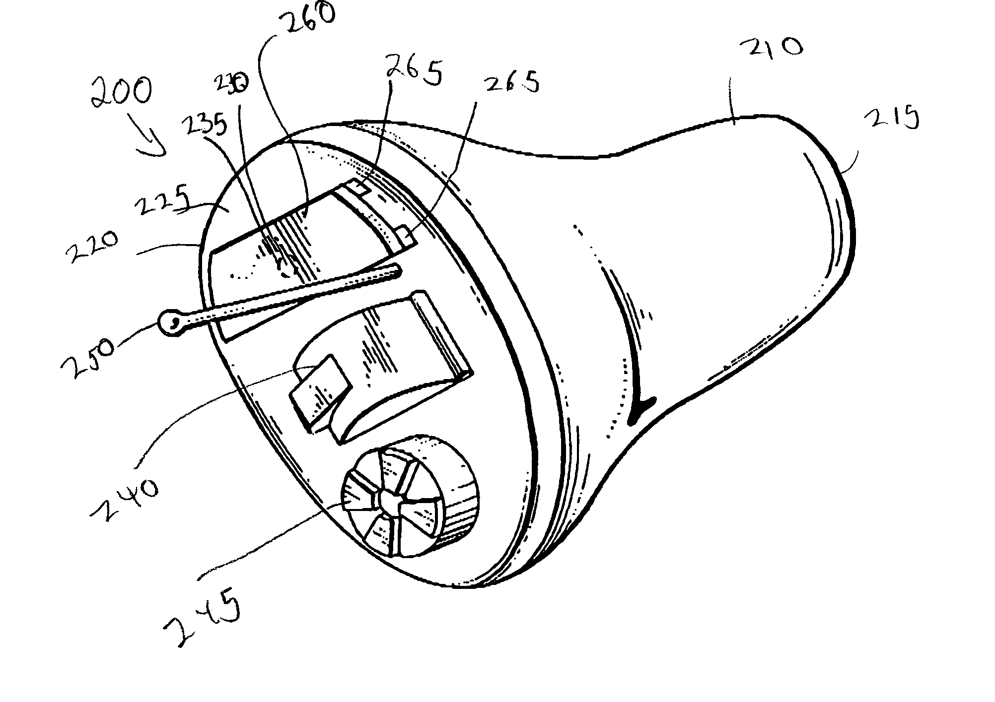
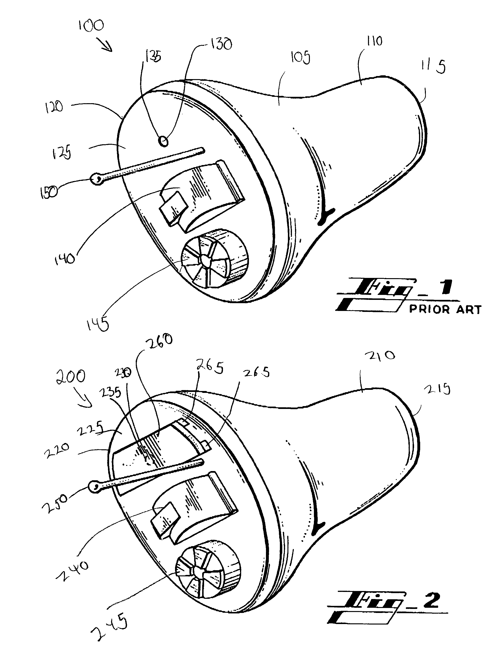
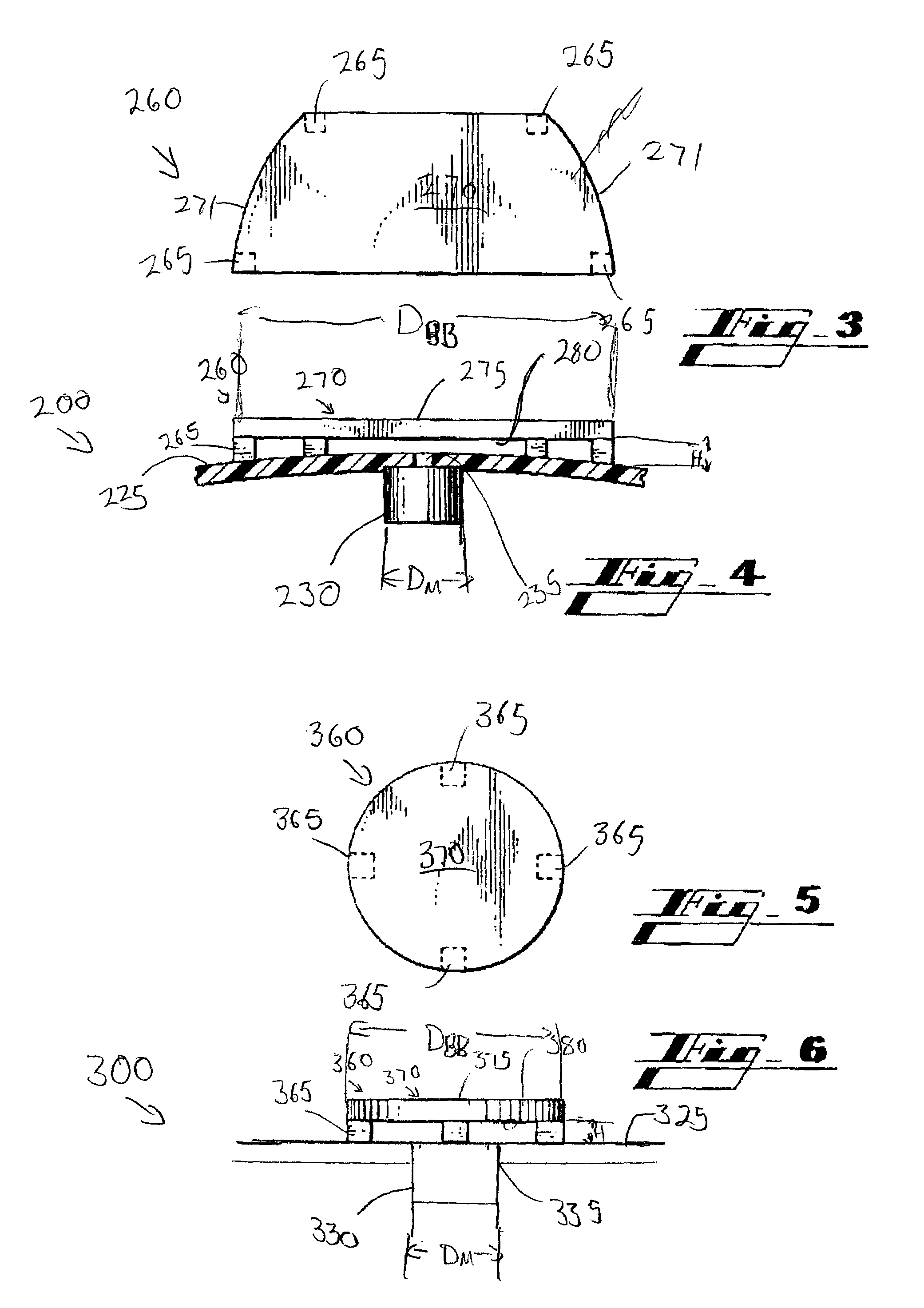
[0048]Referring to the drawings wherein like reference numerals designate corresponding parts throughout the several figures, reference is made first to FIG. 2 that illustrates an embodiment of a three dimensional hearing aid 200.

[0049]The hearing aid 200 shown exemplifies a hearing aid much like a prior art hearing aid to the extent of including a central body 205 having a general shape that is adapted to fit into a user's ear canal, a rear-most portion 210 having a speaker 215, a forward-most portion 220 including a face 225 having operational features of the hearing aid 200. These features include a microphone element 230, a battery door 240, a volume control 245 and a micro-handle 250. The microphone element 230 is typically placed underneath the surface of the face 225 (and can typically be flush the upper surface of the face 225) and an opening 235 the same diameter of the microphone element 230, which allows the sounds to enter to the microphone element 230. In general, the m...


PUM


Abstract

In general, a three dimensional microphone and a three dimensional hearing aid is described. The microphone and hearing aid typically have two boundaries that contribute to the increased frequency response and three dimensional response of the microphone. A microphone element is oriented in and flush with the first boundary which is typically the forward face of a hearing aid. A second boundary, which is typically a boundary button is oriented above and generally parallel with the microphone element creating an overall improvement in frequency response.

Description

BACKGROUND[0001]I. Field of the Invention[0002]The present invention relates generally to the field of acoustics, and more particularly, to a three dimensional microphone apparatus and system and a three dimensional hearing aid.[0003]II. Description of the Related Art.[0004]FIG. 1 illustrates a perspective view of a prior art “In The Ear” (ITE) hearing aid 100. This typical hearing aid 100 includes a central body 105 having a general shape that is adapted to fit into a user's ear canal. The rear-most portion 110 is adapted to fit into the canal closest to the ear drum and includes a speaker 115. The forward-most portion 120 typically protrudes or is flush with the opening of the user's ear. The forward-most portion 120 includes a face 125 that includes operational features of the hearing aid 100. These features include a microphone element 130 that is adapted to receive acoustical spectra (sounds) from the environment. The microphone element 130 is typically placed underneath the su...

Claims


Application Information

Patent Timeline
Patent Type & Authority Patents(United States)
IPC IPC(8): H04R25/00
CPCH04R25/48H04R25/402
Inventor KING, JAMES T.
Owner KING JAMES T
Why Eureka
Try Eureka