Ribbed tube continuous flexible spacer assembly

a flexible spacer and ribbed tube technology, applied in the direction of door/window protective devices, parallel plane units, instruments, etc., can solve the problems of cumbersome prior art practices for manufacturing window assemblies, and inability to provide a flat sightline, etc., to achieve easy production of windows, eliminate longitudinal stretching, and cost-effective

Inactive Publication Date: 2006-09-19
AGC FLAT GLASS NORTH AMERICA INC
View PDF57 Cites 34 Cited by
  • Summary
  • Abstract
  • Description
  • Claims
  • Application Information

AI Technical Summary

Benefits of technology

[0008]There remains a need for an improved continuous spacer assembly that eliminates longitudinal stretching while making it easier to produce a window assembly having a smooth sightline. Moreover, it would be desirable if such a continuous spacer assembly could be fabricated to yield a more cost-effective product while providing the structural stability and benefits of the Greenlee construction. Also, it would be desirable if such assembly allowed for a sharper radius when bending the spacer assembly at the corners.
[0009]Thus, the continuous spacer assembly of the present invention presents advantages by eliminating the amount of necessary sealant material while maintaining the performance of the sealant and spacer strip; eliminating expensive and intricate spacer bar constructions; eliminating the tendency of the material to stretch along its longitudinal axis; reducing thermal conductivity of the insulated window structure by reducing the thermal conductivity of the spacer assembly and providing the necessary ability to form sharper corners.
[0010]It is a further object of the present invention that it be coilable for ease of storage, dispensing and applying to laminate structures such as insulated glass units.

Problems solved by technology

Moisture and organic materials are often trapped inside the sealed air space as a result of the window assembly fabrication process.
Various prior art practices for manufacturing window assemblies are cumbersome, labor intensive or require expensive equipment.
Greenlee's assembly, while addressing previous limitations does not provide a flat sightline once the glass unit is constructed due to undulations in the spacer after the glazed structure are compressed into place.
This stretching can also lead to problems in maintaining a flat sightline.

Method used


Image

  • Ribbed tube continuous flexible spacer assembly
  • Ribbed tube continuous flexible spacer assembly
  • Ribbed tube continuous flexible spacer assembly

Examples


Embodiment Construction

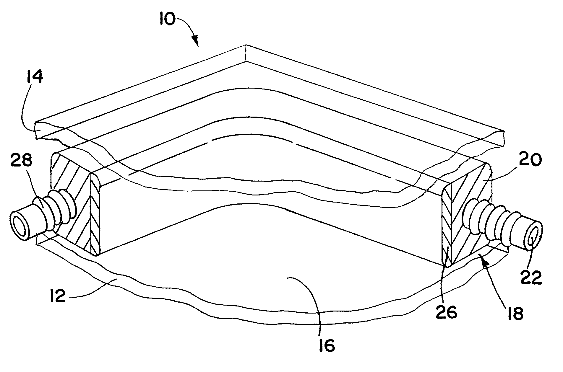
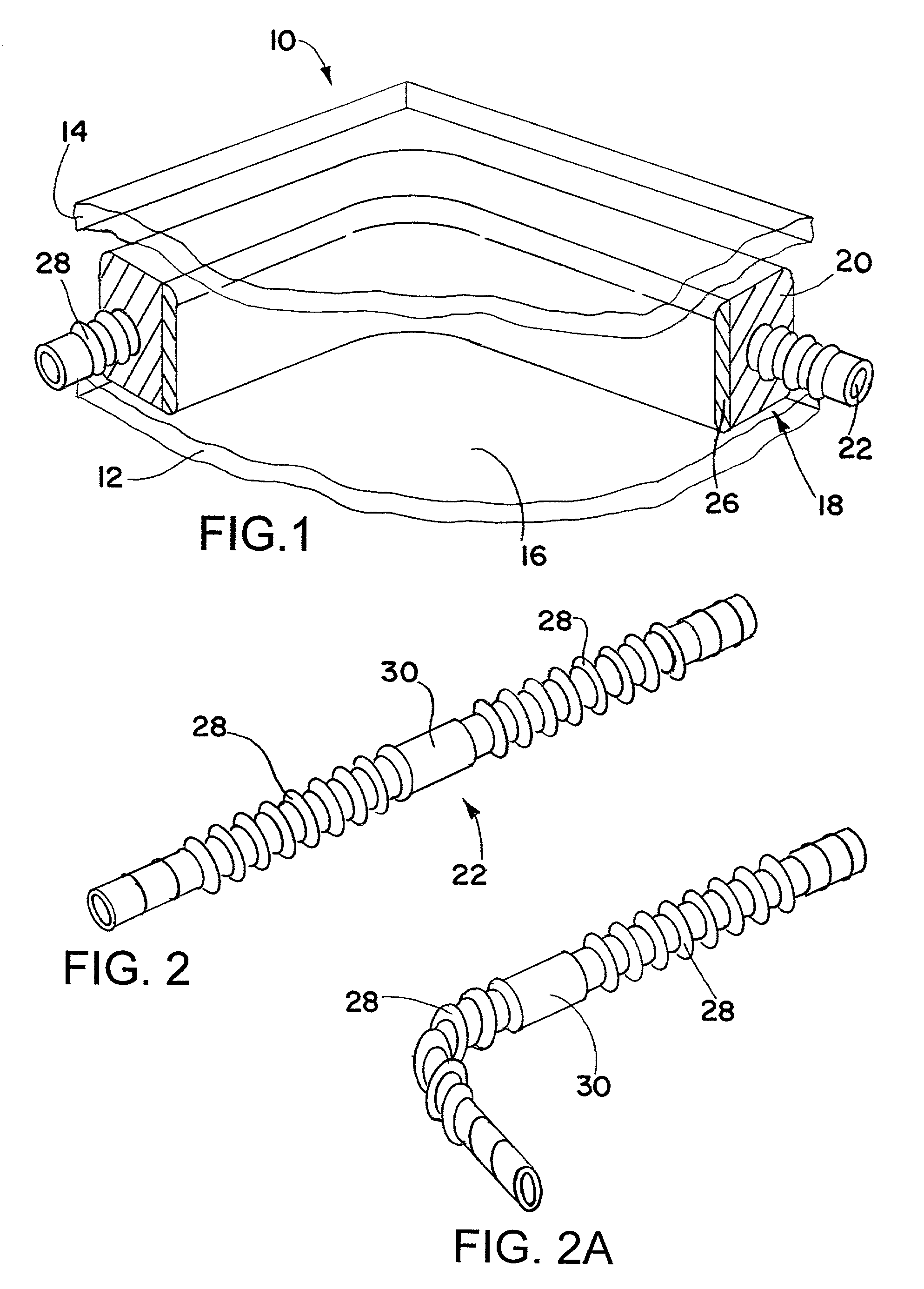
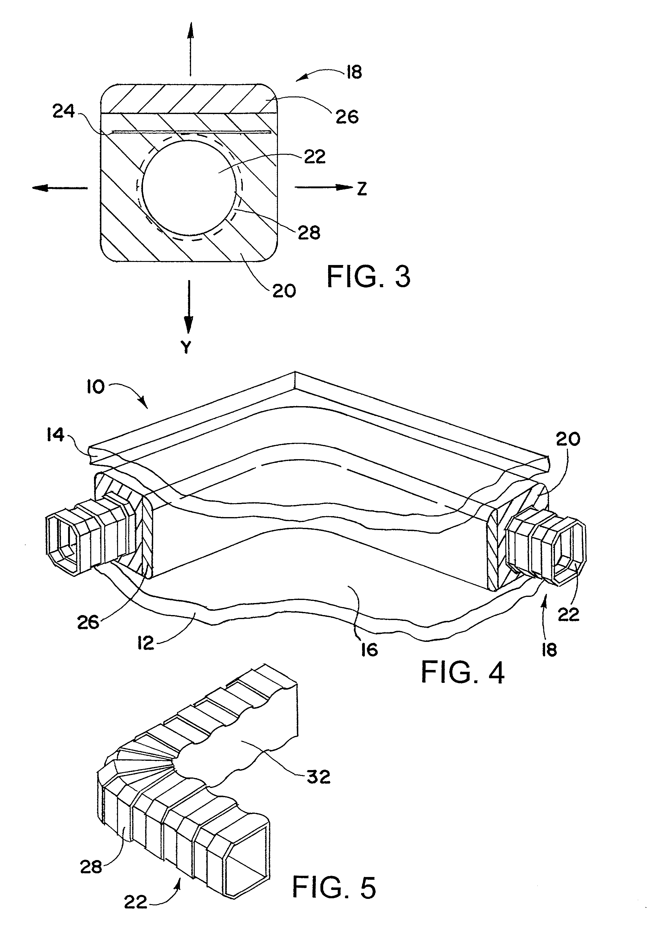
[0020]Referring now to the drawings, it will be seen that FIG. 1 illustrates a composite structure, such as, but not limited to a window assembly, 10 comprising first substrate member 12 and second substrate member 14 having facing, generally parallel surfaces. First and second substrate members 12, 14 are generally glazed structures such as glass panes. The substrate members are 12, 14 joined together to form an enclosed space 16 which is hermetically sealed by a composite tape structure, i.e., spacer / sealant assembly 18, which includes sealant 20 which at least partially envelopes a spacer 22. Glazed structures 12, 14, as illustrated, are formed of glass. It should be appreciated that the invention has applicability in the environment of an unrestricted variety of construction or structural materials, including, for example, cement, concrete, brick, stone, metals, plastics, and wood.

[0021]As illustrated in FIGS. 1 and 4, for purposes of this patent, “interior” means facing into th...


PUM

PropertyMeasurementUnit
flexibleaaaaaaaaaa
areaaaaaaaaaaa
cross-sectional areaaaaaaaaaaa

Abstract

A spacer assembly is disclosed having a spacer with a cross-section varying in a repeating manner along a longitudinal axis and an adhesive sealant at least partially encapsulating the spacer. Also, a moisture vapor barrier may be provided as well as a desiccated topcoat.

Description

[0001]This application claims the benefit of Provisional Application No. 60 / 246,865, filed Nov. 8, 2000.FIELD OF INVENTION[0002]This invention relates to a composite spacer and sealant which can be used particularly in the fabrication of thermally insulating laminates such as windows.BACKGROUND OF INVENTION[0003]In general, the procedure for assembling an insulated window structure involves placing one sheet of a glazed structure over another in a fixed,spaced relationship, and then injecting a sealant composition into the space between the two glazed structures, at and along the periphery of the two structures, thereby forming a sandwich-type structure having a sealed air pocket between the structures. In practice, glazed structures are typically glass but can also be plastic. To keep the glazed structures properly spaced apart, a spacer bar is often inserted between the two structures to maintain proper spacing while the sealant composition is injected into place. Also, the spacer...

Claims


Application Information

Patent Timeline
Patent Type & Authority Patents(United States)
IPC IPC(8): E06B3/66E06B3/64E06B3/663E06B3/673G06Q20/00
CPCE06B3/66314E06B2003/6639E06B3/67313E06B3/66319E06B3/663
Inventor BARATUCI, JAMES LYNNDRDA, PATRICK ANTHONYMILANO, STEVEN MICHAELVAN DE POL, THEO J
Owner AGC FLAT GLASS NORTH AMERICA INC
Why Eureka
Try Eureka