Upper decorative stitching device

a stitching device and decorative technology, applied in the direction of sewing machine elements, automatic machines, transportation and packaging, etc., can solve the problems of difficulty in accurately reflecting the swing motion of the first lever, and cost elevation

Active Publication Date: 2006-09-19
JANOME CORP
View PDF6 Cites 5 Cited by
  • Summary
  • Abstract
  • Description
  • Claims
  • Application Information

AI Technical Summary

Benefits of technology

[0005]The second feature of the invention is to provide an upper decorative stitching device having a simple structure which permits easier changeover of the stitching mode between the upper decorative stitching and the other mode, e.g., flat seam stitching, by making it possible for a thread guide supporting member having at the lower end a thread guide for feeding upper decorative thread to the spreader to be switched over between the thread feeding position and the non-feeding position.
[0006]The third feature of the invention is that the thread guide supporting member is fixed to the front end of the mounting shaft whose front and rear ends are borne by the frame having a second lever, and is forced by coil springs whose front and rear ends are borne by the thread guide cam and the bearings, and, mediated by engagement between a plurality of the recesses and projections disposed on the opposed surfaces of the thread guide cam and the frame, in an ordinary time the thread guide supporting member shall be held perpendicularly to the thread feeding position, and when no upper decorative stitching thread is fed it shall be obviated nearly horizontally to the front right side of the sewing machine and held in a non-feeding position, then engaging the thread guide supporting member displaced to the non-feeding position with the first lever by way of engagement between the recesses and the projections, and separating the first lever from the swing width cam by engaging the thread guide supporting member displaced to the non-feeding position with the first lever to stop the operation of the spreader, thereby expecting to make the changeover operation more rapid and to obtain stability at the changeover position.
[0008]A thread guide supporting member having at its lower end a thread guide for feeding an upper decorative stitching thread to a spreader is provided so as to make it possible to be switched over between the thread feeding position and the non-feeding position.

Problems solved by technology

As the upper decorative stitching device is made to connect the spot between the first lever which shows swing movements widthwise in a pendulum style in front of the sewing machine and the second lever which reciprocates horizontally along the needle position with a plate form connecting rod, there were movements up and down caused by the connecting rod at one end and the other end of the swinging step of the first lever, thereby making it difficult to reflect the swing motion of the first lever accurately on the movements of the second lever which should reciprocate horizontally.
Moreover, as the upper decorative stitching device is made to change the stitching mode between the upper decorative stitching and the other stitching, e.g., flat seam stitching, by the switching operation of the clutch provided between the upper shaft and the swing width cam, machine construction is complicated which results in elevation of cost.

Method used


Image

  • Upper decorative stitching device
  • Upper decorative stitching device
  • Upper decorative stitching device

Examples


Embodiment Construction

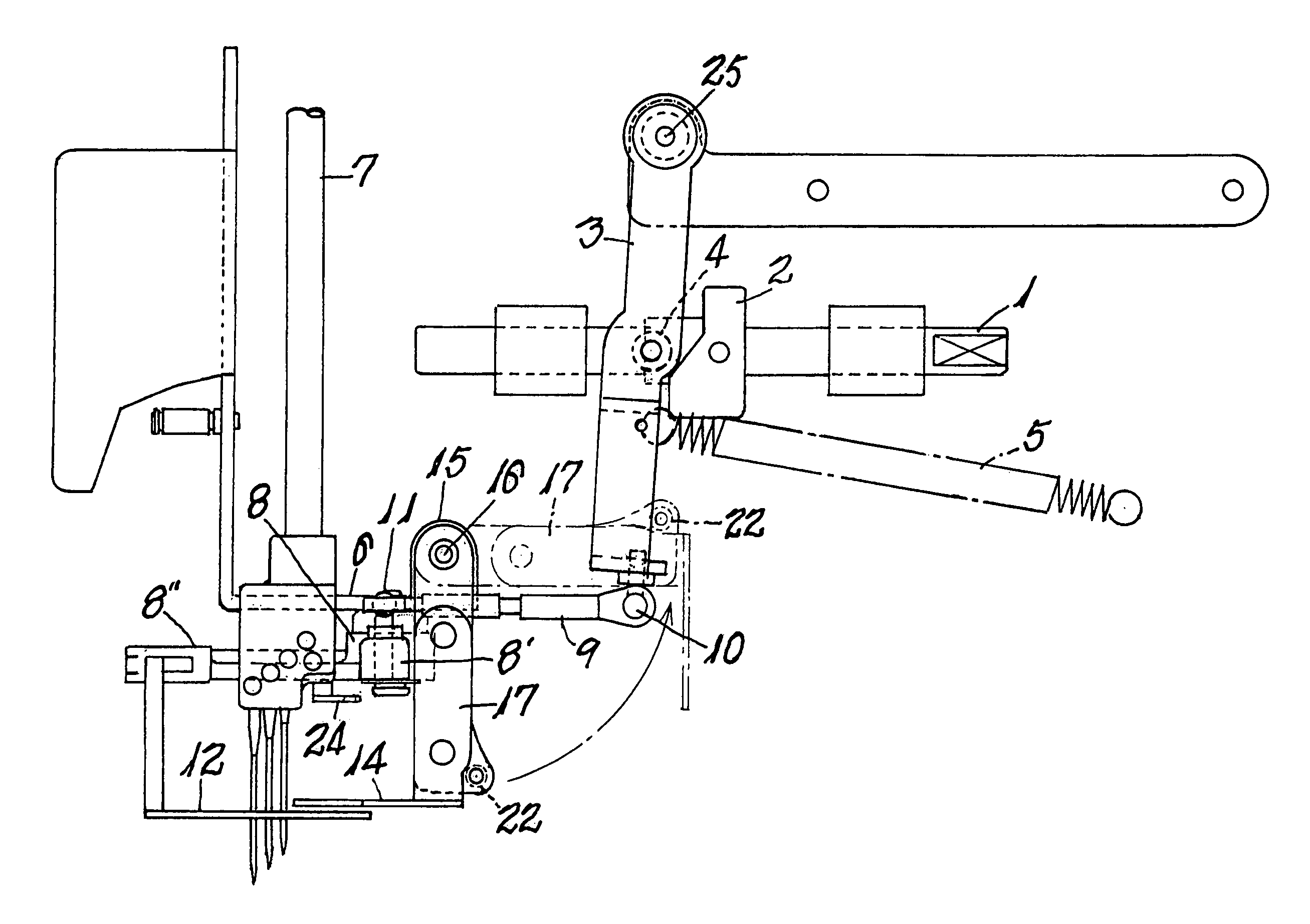
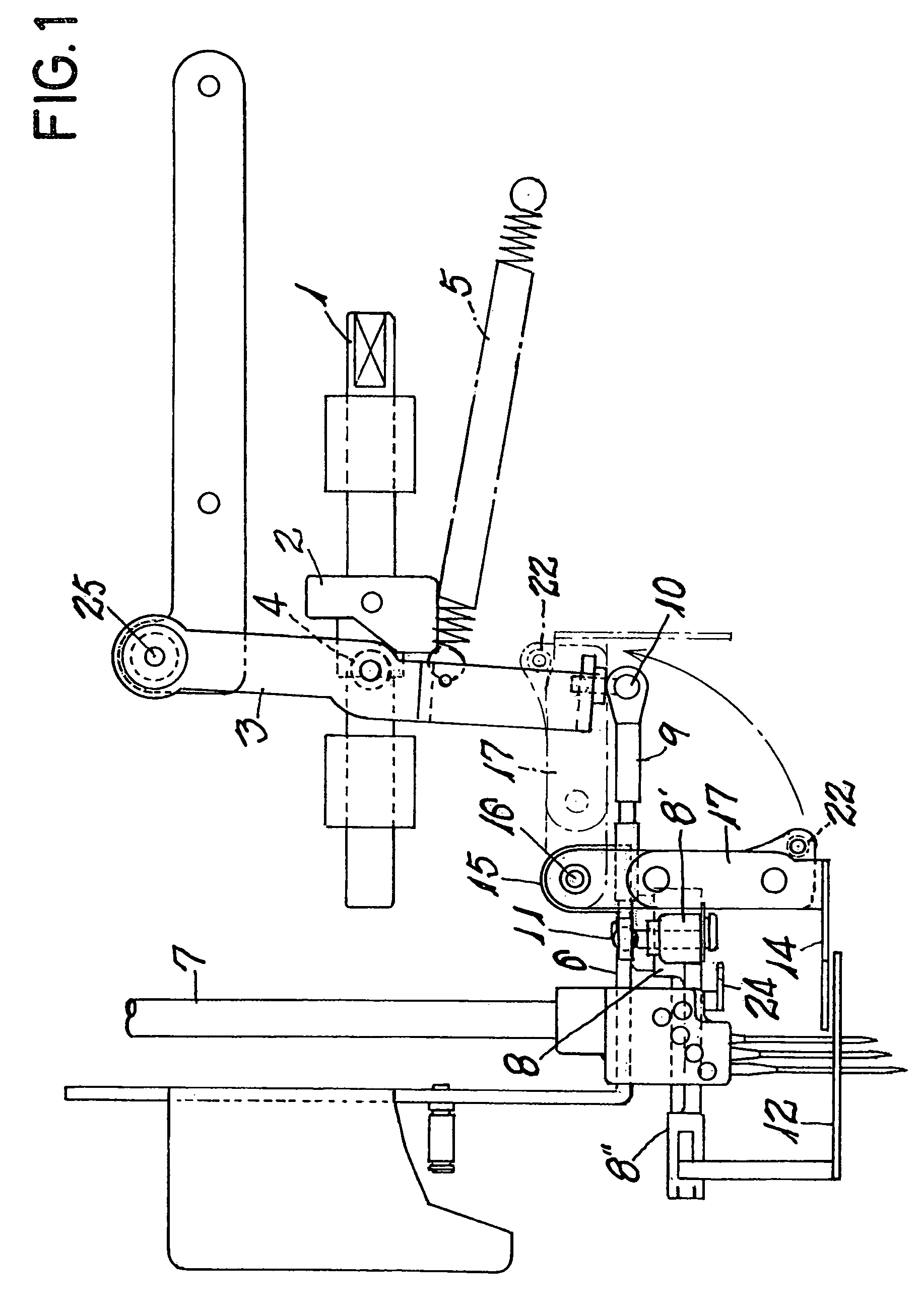
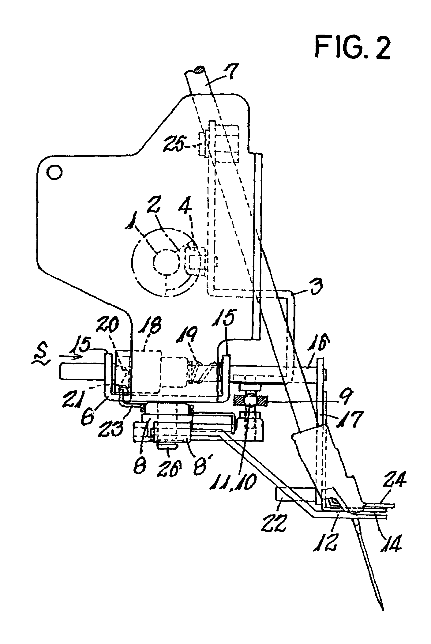
[0013]Next, explanation will be given of embodiments of the present invention in accordance with the accompanying drawings.

[0014]FIG. 1 is a partial cutaway front view of the upper decorative stitching device according to the present invention, FIG. 2 is a partial cutaway side view of the device, and FIG. 3 is a partial cutaway plan view showing mainly the driving portion of the spreader.

[0015]In the drawings showing the embodiments, reference numeral 1 designates an upper shaft which repeats reciprocal semi-rotation along with the driving of the sewing machine, a swing width cam 2 is fixed to the upper shaft 1, a first lever 3 which moves in a swinging motion widthwise in front of the sewing machine along with the rotation of the upper shaft 1, a frame 6 is formed on the right side in the illustration rearward of the elevating position of the needle bar 7, a bell crank type second lever 8, borne on the reverse surface of the frame 6, is provided in a freely swinging manner in a hor...


PUM


Abstract

An upper decorative stitching device is designed to make it possible to precisely transmit the swing movement of a first lever which is capable of swing movements widthwise in a pendulum manner to horizontal reciprocating motion of a second lever, which is provided with a spreader. The device facilitates the operation of switching between an upper decorative stitching and no upper decorative stitching. A connecting rod (9) is provided at both ends with spherical bearings (10, 11) to provide a connection between the first lever (3) and the second lever (8), thereby converting the rotation of the upper shaft into the reciprocal movement of the spreader.

Description

BACKGROUND OF THE INVENTION[0001]The present invention relates to an upper decorative stitching device to be provided mainly on a flat seam stitching machine. Its object is to make it possible to convey precisely the swing movements of the first lever which shows swing movements widthwise in a pendulum style to the horizontal reciprocating motion of the second lever provided with a spreader, to make it possible to reduce the cost of the device by simplifying the structure of the upper decorative stitching device, and also to facilitate the switching operation between the case of the upper decorative stitching and the case of the flat seam stitching.[0002]As an upper decorative stitching device having a first lever which shows swing movements widthwise in a pendulum style in front of the sewing machine by a swing width cam provided on an upper shaft and a second lever having a spreader at the front end which also reciprocates horizontally with the other end of the connecting rod conn...

Claims


Application Information

Patent Timeline
Patent Type & Authority Patents(United States)
IPC IPC(8): D05B3/12D05B69/02
CPCD05B1/08D05B61/00D05D2303/08
Inventor HASEGAWA, SHOGO
Owner JANOME CORP
Why Eureka
Try Eureka