Transmission and method for controlling a transmission with at least one shift control element

Inactive Publication Date: 2006-09-19
ZF FRIEDRICHSHAFEN AG
View PDF8 Cites 18 Cited by
  • Summary
  • Abstract
  • Description
  • Claims
  • Application Information

AI Technical Summary

Benefits of technology

[0009]According to the invention, since the coupling device in the transmission is additionally made with a synchromesh device and before the positive-locking element of the coupling is closed, it can be synchronized and the positive-locking element of the coupling can then be engaged without noise emission and without large force.
[0010]Furthermore, the construction of the coupling with a synchromesh has the advantage that the positive-locking action of the coupling can be engaged in any operating conditions, i.e., with any speed difference between the two halves of the positive-locking device, since such differences can be equalized by the synchromesh in a simple way.
[0011]In addition, drag torques that occur due to fluid friction between the halves of the shift control element when the latter is open, are reduced because the transmission components of at least one half of the shift control element are uncoupled when the coupling is open, and the drag torques, occurring at the synchromesh, are considerably smaller than those between the halves of the shift control element when the transmission components

Problems solved by technology

A disadvantage in this, however, is that the positive-locking coupling between the inner disc carrier of the disc brake and the planetary gearwheel support of the planetary gear assembly can only be closed comfortably when the rotation speeds of the said inner disc carrier and planetary gearwheel support are equal.
If there is a speed difference between the inner disc carrier and the planetary gearwheel support, t

Method used


Image

  • Transmission and method for controlling a transmission with at least one shift control element
  • Transmission and method for controlling a transmission with at least one shift control element
  • Transmission and method for controlling a transmission with at least one shift control element

Examples


Example

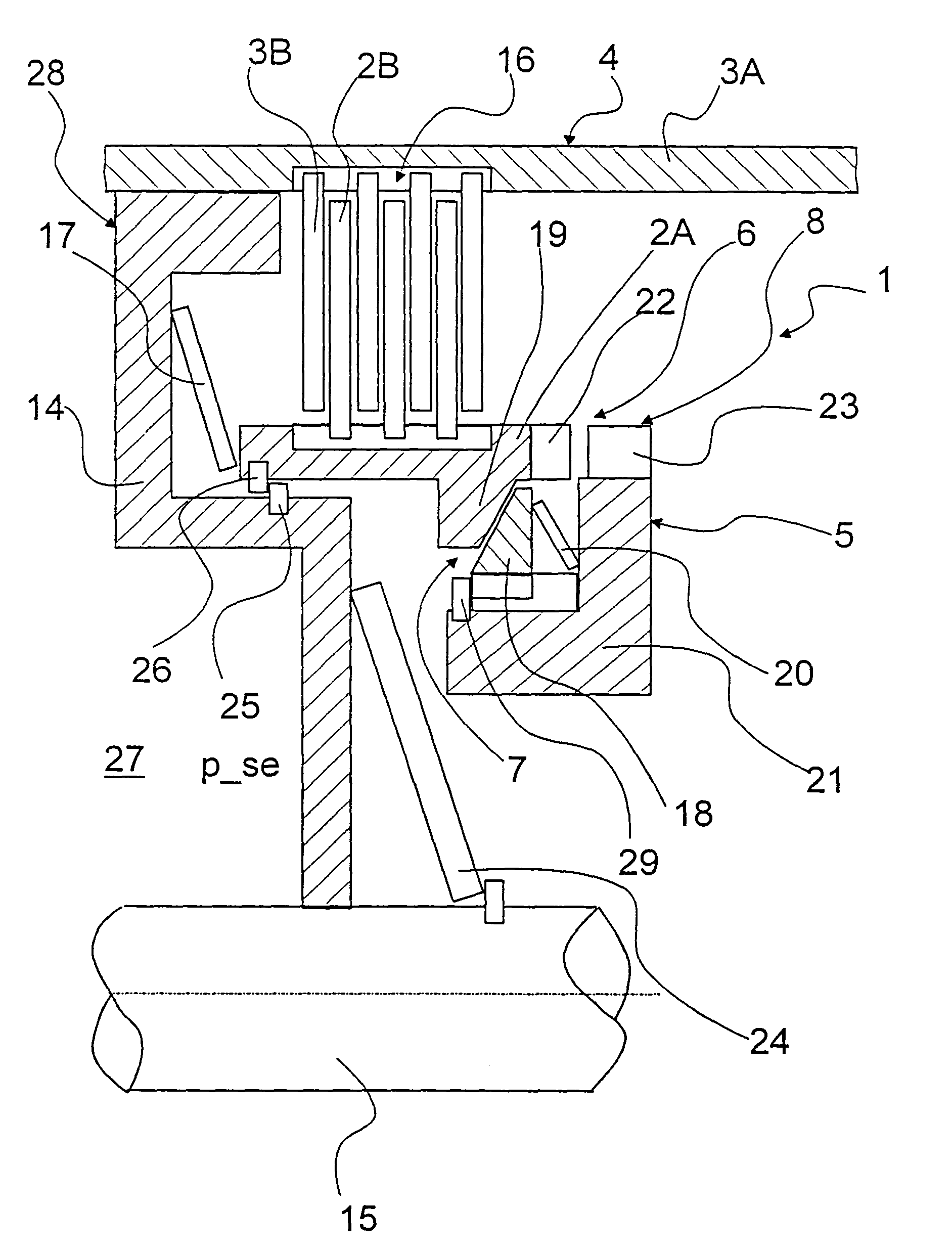
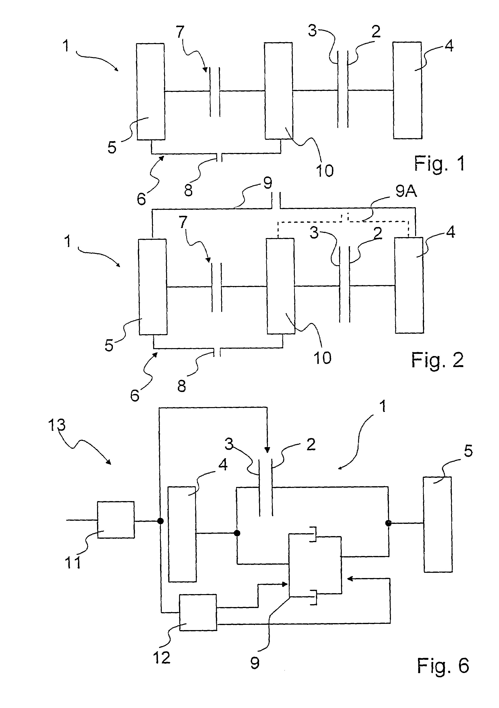
[0023]FIG. 1 shows a shift control element 1 of a transmission (not illustrated in further detail), which is constructed as a variable-speed automatic transmission. The shift control element 1 is provided in order to engage one or more gears of the variable-speed automatic transmission, and is engaged in or disengaged from a power train as a function of a required transmission ratio of the variable-speed automatic transmission. The shift control element 1 comprises a first shift control element half 2 and a second shift control element half 3, which can be brought into force-locking or frictional engagement with one another.

[0024]The halves 2, 3 of the shift control element 1 are connected to non-rotating 4 and rotating 5 transmission components. Between the first half 2 of the shift control element 1 and the rotating transmission components 5 connected to it, a positive-locking coupling device 6 is provided, which is also made with a synchromesh device 7.

[0025]In the closed conditi...


PUM


Abstract

A transmission is described, in particular an automatic transmission for a vehicle, having at least one shift control element formed at least of a second shift control element half that can be brought into active frictional engagement with a first shift control element half. The shift control element halves can be connected to non-rotating and rotating transmission components, and a positive-locking coupling device is provided at least between the first shift control element half and the transmission components that can be connected thereto. The coupling device also comprises a synchromesh device. In addition, a method is described for controlling a transmission that has at least one shift control element and two shift control element halves which can be brought into active frictional engagement. When it is necessary to close the shift control element, the coupling device is synchronized by a synchromesh device, a positive-locking function of the coupling device is closed, and the halves of the shift control element are frictionally engaged.

Description

FIELD OF THE INVENTION[0001]The invention concerns a transmission and a method for controlling a transmission with at least one shift control element, which has at least two shift control element halves that can be brought into active, positive-locking engagement with one another.BACKGROUND OF THE INVENTION[0002]From DE 100 40 116 A1 a transmission of the type described at the start is known, in which a positive-locking coupling is provided between an inner disc carrier of a multiple-disc brake and a planetary gearwheel support of a planetary gear assembly. When the disc brake is open the positive-locking coupling is opened to uncouple transmission components from the disc brake in order to reduce drag torques.[0003]When it is required to close the multiple-disc brake, the positive-locking coupling is closed without force by an axial piston so that the transmission components or planetary gear support and the transmission components, in turn, actively connected thereto are coupled t...

Claims


Application Information

Patent Timeline
IPC IPC(8): F16D23/02F16H63/30F16D23/06F16D25/0638F16H61/04F16H61/30F16H61/682
CPCF16D23/06F16D25/0638F16H61/0403F16H61/30F16H2306/50F16H63/3026F16H2306/46F16H2306/48F16H61/682
Inventor EBENHOCH, MICHAELBAASCH, DETLEFDREIBHOLZ, RALF
Owner ZF FRIEDRICHSHAFEN AG
Why Eureka
Try Eureka