[0012]Accordingly, it is the object of the invention to provide a plating treatment technique which permits uniform plating treatment and easy replacement of articles to be plated without the effect of bubbles in a plating solution by improving wet plating apparatuses differentiated as “the
contact type” to thereby solve problems such as the removal of bubbles in a plating solution and the removal of an adhering plating solution.
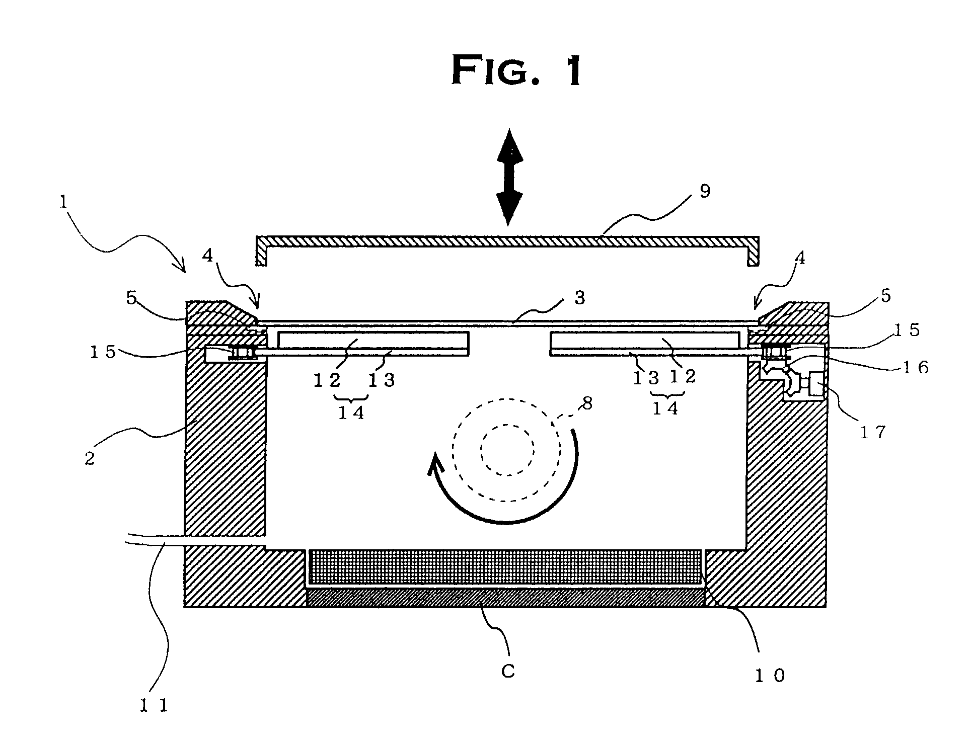
[0014]Because the plating apparatus of the invention is provided with rotational means for rotating the plating tank itself, an article to be plated is placed on the opening of the plating tank in the same condition as with “the top placement type” and after that, the plating tank is rotated, whereby the positional relationship between the article to be plated and the plating solution is changed as with “the bottom arrangement type,” enabling plating treatment to be performed by ensuring that bubbles in the plating solution is prevented from having an effect on the object plating surface of the article to be plated. And after plating treatment, it is possible to replace articles to be placed in such a condition that the plated article placed on the opening of the plating tank is on the top side and the plating tank is on the bottom side, that is, by rotating the plating tank to the same condition as with “the top placement type.”
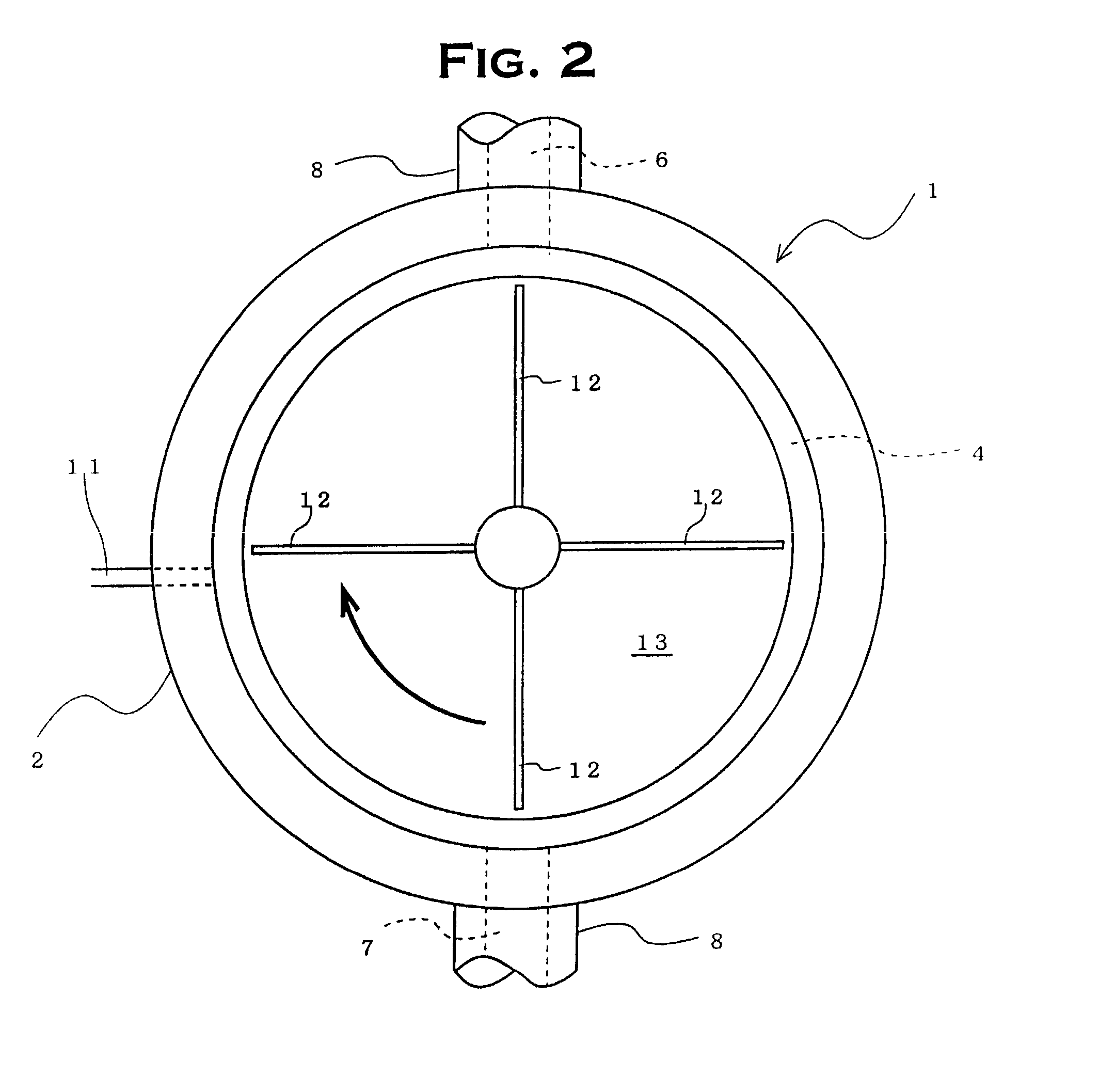
[0016]There is no limitation to the rotational motion of the plating tank itself in the plating apparatus of the invention, and the rotational angle and frequency of rotations during plating treatment can be appropriately selected. For the rotation of the plating tank, for example, the plating tank may be rotated through 90 degrees so that an article to be plated, which is placed on the opening, is brought into a standing condition or the plating tank may be rotated through 180 degrees so that the article to be plated is brought into a reverse condition, i.e., the condition as with “the bottom arrangement type.” Furthermore, the rotational motion may be performed repeatedly during plating treatment, and the plating tank may be rotated in a continuous rotational motion. In short, it is necessary only that by rotating the plating tank itself, bubbles in the plating solution be prevented from exerting an adverse influence on the target plating surface of an article, which is subjected to plating treatment.
[0017]According to this plating apparatus of the invention, it is no longer necessary to take the measures to remove bubbles hitherto carried out in “the top placement type,” for example, the removal of bubbles by increasing the supply flow rate of plating solution thereby to
discharge a large amount of plating solution and the
elimination of the effect of bubbles on an article to be plated by arranging an
anode bag, a diaphragm, etc. within the plating tank. That is, plating treatment is possible without the effect of bubbles in the plating solution even when the supply flow rate of plating solution is small and even when special measures to remove bubbles are not taken. Furthermore, because plating treatment is carried out in a condition not affected by bubbles as with “the bottom arrangement type” during plating treatment and the condition in the case of “the top placement type” can be recovered after the completion of the treatment, the replacement of articles to be plated can be easily carried out and the adherence of the plating solution to the articles to be plated can be reduced.
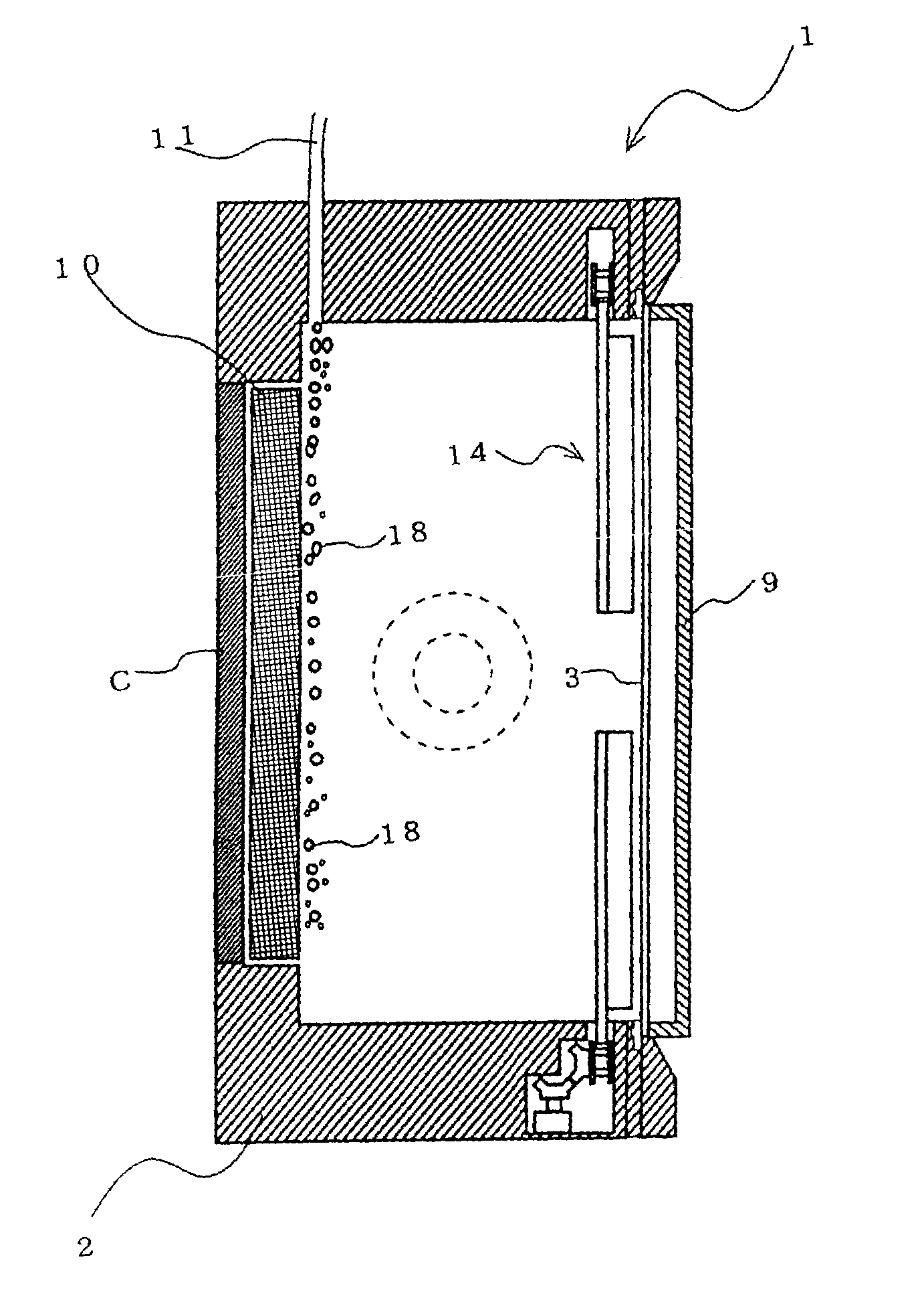
[0018]And in the plating apparatus of the invention, it is preferred that a bubble-vent hole be provided in the plating tank. When a bubble-vent hole is provided in the plating tank, the plating tank is rotated in such a manner that this bubble-vent hole assumes a top position, and plating treatment is carried out in this state, bubbles in the plating solution ascend toward the bubble-vent hole and it becomes possible to efficiently remove the bubbles from the plating solution.
[0021]In addition, it is preferred that in the plating apparatus related to the invention, part of the wall of the plating tank can be opened and closed. When part of the wall of the plating tank can be opened and closed, by rotating the plating tank, the tank wall portion which can be opened and closed is caused to assume a top position. By opening the tank wall portion in that position, it is possible to easily carry out maintenance within the plating tank, such as anode replacement, even when all plating solution is not discharged to outside the plating tank. It is especially preferred in terms of practical use that this tank wall which can be opened and closed be provided on the side of the tank wall where the anode is provided. The anode disposed in a position opposite to an article to be plated needs to be replaced after a certain plating treatment when the anode is a soluble one. Even when the anode is an insoluble one, maintenance such as replacement and cleaning is required because
black films etc. adhere to the anode surface after a long period of plating treatment. For this reason, when the tank wall on the side where this anode is disposed can be opened and closed, by rotating the plating tank thereby to cause this tank wall which can be opened and closed to assume a top position, it is possible to easily carry out maintenance work such as anode replacement by opening the tank wall.

