Three-phase ac generator for vehicle

a technology of alternating current and electric generator, which is applied in the direction of electric generator control, dynamo-electric converter control, semiconductor/solid-state device details, etc., can solve the problems of increasing the number of parts built in the electric generator, difficult to make the connection work, and difficulty in making the connection work, so as to simplify the connection work of each generating coil and each diode pair, and simplify the internal construction of the electric generator.

Inactive Publication Date: 2006-09-19
MITSUBISHI ELECTRIC CORP
View PDF17 Cites 13 Cited by
  • Summary
  • Abstract
  • Description
  • Claims
  • Application Information

AI Technical Summary

Benefits of technology

[0015]The neutral diode having the first, second and third connecting terminals commonly connected to each other is used in the three-phase alternating current electric generator for a vehicle in this invention. The coil terminals of the neutral side of the A-phase, B-phase and C-phase generating coils of the three phases are respectively connected to the first, second and third connecting terminals of the above neutral diode. The connecting work of the neutral diode and the coil terminal of the neutral side of each generating coil is simplified. The coil terminals of the neutral side of the generating coils of the three phases are respectively connected to the first, second and third connecting terminals of the neutral diode one by one, and the connecting work is simplified. Further, since no special circuit substrate is used, the internal construction of the electric generator can be simplified.
[0018]In the another three-phase alternating current electric generator for a vehicle in this invention, the rectifier assembly has the first, second and third diode pairs. Each of these diode pairs has the first and second connecting terminals commonly connected to each other. The coil terminal of the generating coil of each phase is connected to the first and second connecting terminals of the first, second and third diode pairs. As a result, the connecting work of each generating coil and each diode pair is simplified. The first and second coil terminals of the generating coil of each phase are respectively connected to the connecting terminals of each diode pair one by one, and the connecting work is simplified. Further, since no special circuit substrate is used, the internal construction of the electric generator can be simplified.

Problems solved by technology

In the construction for connecting the three coil terminals of the neutral side to one diode, all the three coil terminals are connected to one connecting terminal of the diode as a result so that it is difficult to make its connecting work.
It is difficult to make such a connecting work.
This circuit substrate causes an increase in the number of parts built in the electric generator and makes the internal arrangement of a bracket complicated.
Accordingly, it is also difficult to make this connection.
However, the number of parts is increased and the internal structure of the bracket is complicated by using the circuit substrate.

Method used


Image

  • Three-phase ac generator for vehicle
  • Three-phase ac generator for vehicle
  • Three-phase ac generator for vehicle

Examples


first embodiment

Entire Explanation of First Embodiment

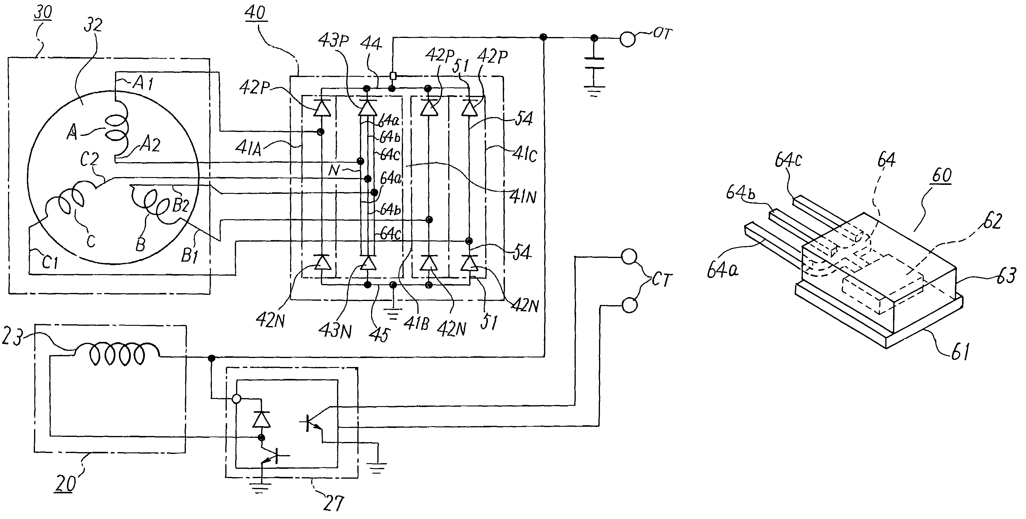
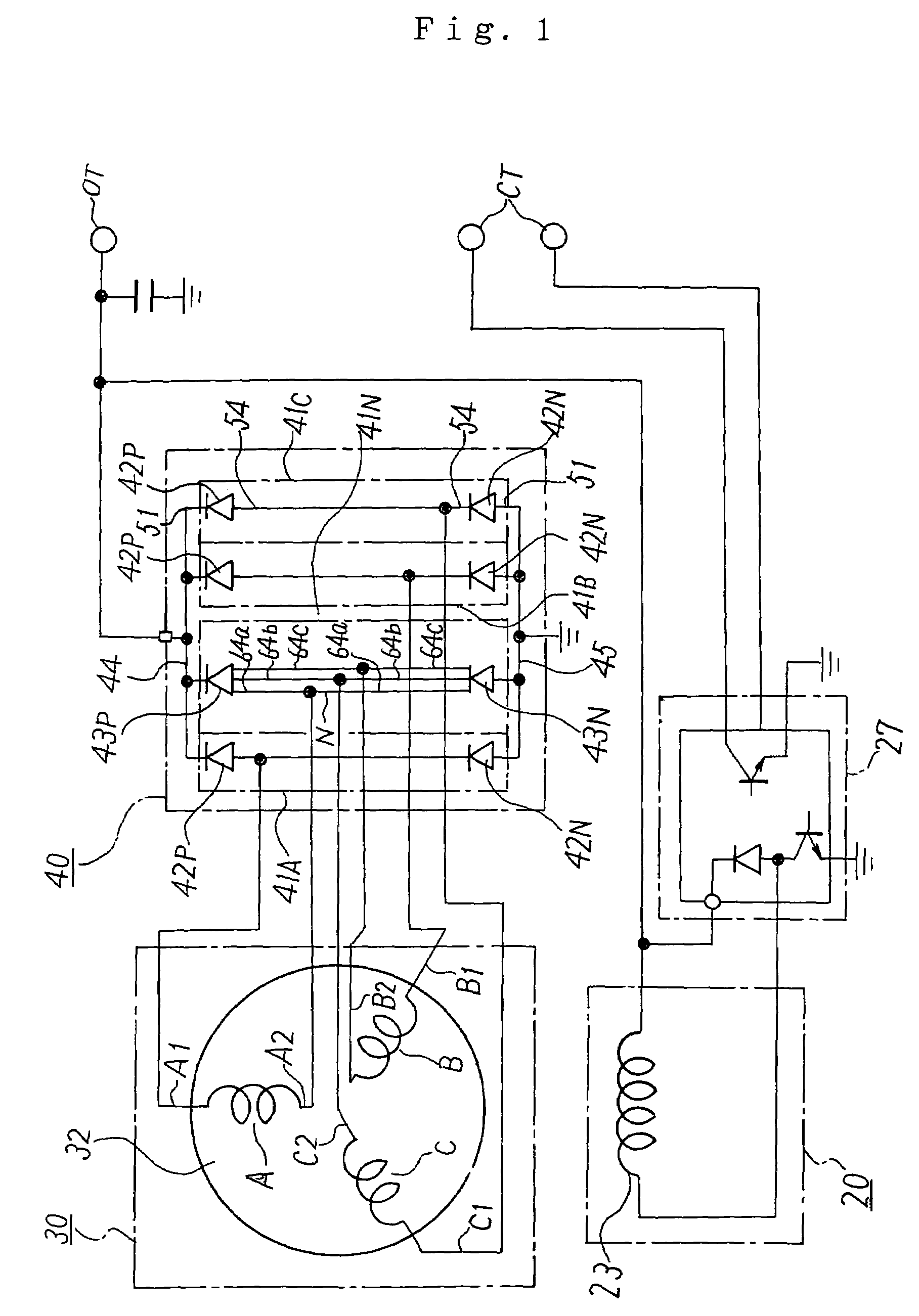
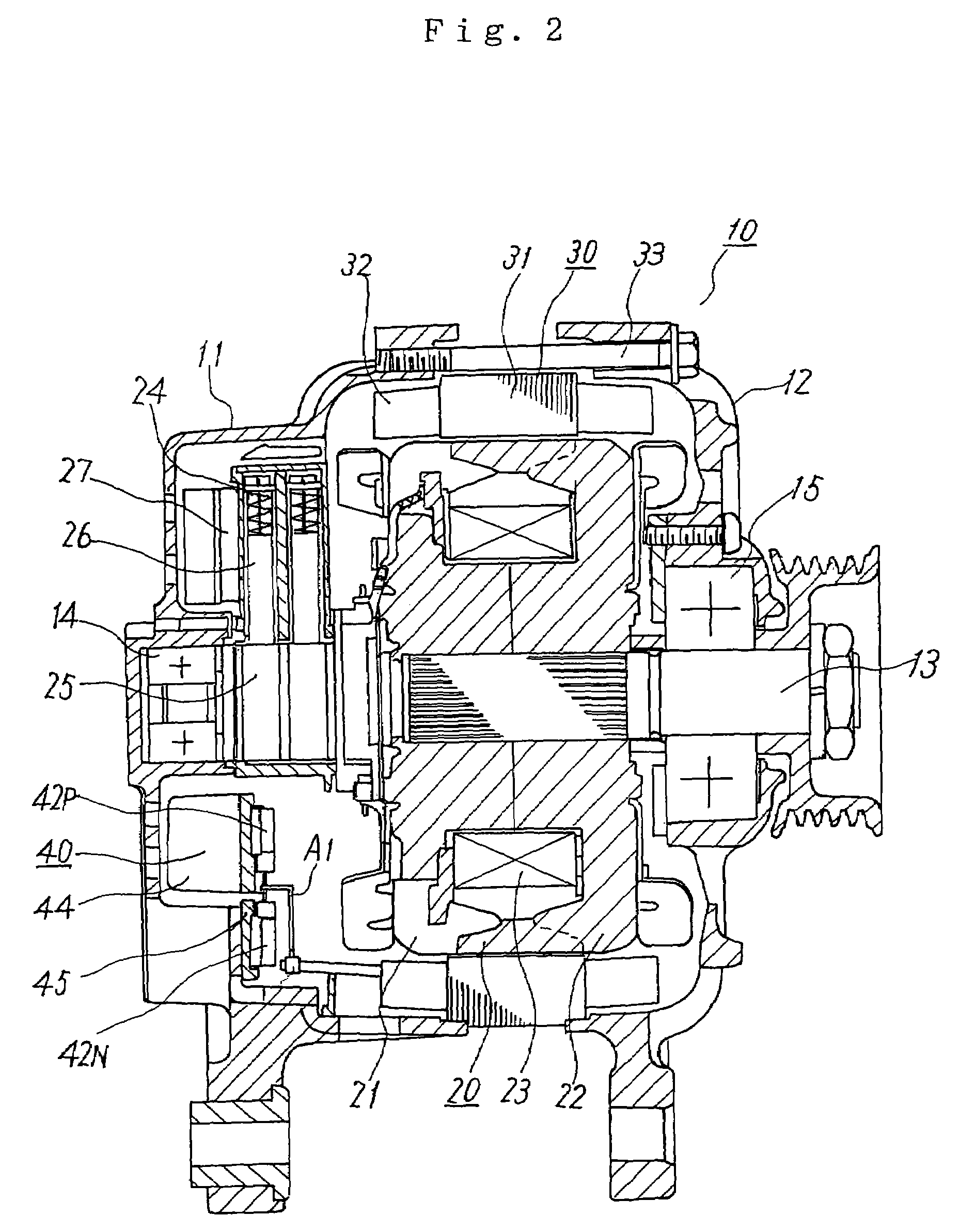
[0035]The three-phase alternating current electric generator 10 for a vehicle shown in FIGS. 1 and 2 is a three-phase alternating current electric generator of a Y-shape connecting type. This three-phase alternating current electric generator 10 has a pair of brackets 11, 12, a rotating shaft 13, a rotor 20, a stator 30 and a rectifier 40. The rotating shaft 13 is rotatably supported by the pair of brackets 11, 12 through ball bearings 14, 15. This rotating shaft 13 is operated by an engine mounted to the vehicle, and the rotor 20 is fixed to this rotating shaft 13.

Explanation of Rotor 20 of First Embodiment

[0036]This rotor 20 is a rotating field magnet and has a pair of field magnet ion cores 21, 22 and a field magnet coil 23. The field magnet coil 23 is magnetized by an unillustrated battery mounted to the vehicle through an electricity supply mechanism 24. This electricity supply mechanism 24 has a pair of slip rings 25 arranged in the rotati...

second embodiment

Explanation of Second Embodiment

[0052]In the first embodiment, the package structure 60 shown in FIG. 5 is adopted as the neutral diodes 43P, 43N. However, in the second embodiment, a package structure 60A shown in FIG. 7 is used as the package structure of the neutral diodes 43P, 43N. In this package structure 60A of FIG. 7, first, second and third connecting terminals 64a, 64b, 64c are electrically commonly connected to each other in the exterior of a resin package 63 with respect to the drawing-out terminal 64. The other constructions of the package structure 60A are the same as the package structure 60 of FIG. 5. This package structure 60A of FIG. 7 is also adopted in the neutral diode 43P of the positive side and the neutral diode 43N of the negative side. The anode and the cathode of the diode chip 62 are similarly arranged so as to be reverse to each other in the diodes 43P and 43N.

[0053]In accordance with this second embodiment, the same effects as the first embodiment can b...

third embodiment

Explanation of Third Embodiment

[0054]In this third embodiment, a composite type neutral diode 70 having a package structure shown in FIG. 8 is used instead of the neutral diodes 43P, 43N of the first embodiment. This neutral diode 70 of FIG. 8 is a composite type diode constructed such that the neutral diode 43P of the positive side and the neutral diode 43N of the negative side in the first embodiment are stored into one package. A diode pair 41N for making the neutral point connection is constructed by this one composite type diode 70.

[0055]In this neutral diode 70, two diode chips 72A, 72B and an intermediate electrically conductive substrate 73 are nipped between a pair of electrically conductive substrates 71A, 71B opposed to each other. The intermediate electrically conductive substrate 73 is nipped so as to be located just in an intermediate position of the two diode chips 72A, 72B. The diode chip 72A is a diode chip of the positive side, and is arranged between the electrica...


PUM


Abstract

A neutral point diode having three connecting terminals electrically commonly connected to each other is used in a type for connecting each generating coil of a three-phase alternating current electric generator for a vehicle in a Y-shape connection. The coil terminal of a neutral point side of each generating coil is connected to each of the three connecting terminals of this neutral point diode. A diode having two connecting terminals electrically commonly connected to each other is used in a type for connecting each generating coil in a Δ-shape connection. The coil terminals of two adjacent generating coils are connected to the respective two connecting terminals of this diode. In both the types, one coil terminal is connected to one connecting terminal and a connecting work is simplified.

Description

TECHNICAL FIELD[0001]This invention relates to a three-phase alternating current electric generator for a vehicle mounted to the vehicle and used to charge a battery mounted to the vehicle and supply electricity to other electric loads for the vehicle, and particularly relates to a three-phase alternating current electric generator for a vehicle building-in a rectifier assembly for rectifying an alternating current output of each of generating coils of the three phases.BACKGROUND ART[0002]A Y-shape connection for connecting the respective generating coils of the three phases in a star shape (Y-shape), and a Δ-shape connection for connecting the respective generating coils of the three phases in a delta shape (Δ-shape) are known as the three-phase alternating current electric generator for a vehicle building-in the rectifier assembly of this kind.[0003]First, the three-phase alternating current electric generator for a vehicle of the conventional Y-shape connection will be explained....

Claims


Application Information

Patent Timeline
Patent Type & Authority Patents(United States)
IPC IPC(8): H02H7/06H02K11/00H02K11/04H02P11/00H02P9/00H01L25/11H02K3/28H02K19/36
CPCH01L25/115H02K11/046H02K19/36H01L23/49562H02K3/28H01L2924/0002H01L2924/00H02K11/05
Inventor KASHIHARA, TOSHIAKI
Owner MITSUBISHI ELECTRIC CORP
Why Eureka
Try Eureka