DC-offset transient response cancel system

a transient response and cancel technology, applied in pulse manipulation, pulse technique, instruments, etc., to achieve the effect of reducing the time constant of high pass filter and degrading voice quality

Inactive Publication Date: 2006-09-19
PANASONIC CORP
View PDF7 Cites 3 Cited by
  • Summary
  • Abstract
  • Description
  • Claims
  • Application Information

AI Technical Summary

Benefits of technology

[0015]An object of the present invention is to provide a DC-offset transient response cancel system which eliminates a DC-offset transient response and accordingly sets a DC value to a steady value instantaneously.
[0016]To achieve the object, the DC-offset transient response cancel system according to the present invention uses a circuit which detects a change of a gain control signal. The DC-offset transient response cancel system further uses a counter and a clock generator which are for generating a cancel pulse which has a certain width after detecting a change of the gain control signal. The DC-offset transient response cancel system still further uses a switch which cuts a signal at the timing of the cancel pulse, and also a switch which shorts a resistor which is involved in later-stage capacitance-coupling (high pass filter) at the timing of the cancel pulse. This permits cutting an AC signal only right after a change in gain and accordingly reducing the time constant of the high pass filter, which in turn realizes elimination of a transient response of a DC offset.
[0024]The present invention makes it possible to decrease the time constant of the high pass filter during a certain period of time since the gain control signal has changed. This eliminates a transient response of a DC offset which will degrade the voice quality. In this manner, an excellent DC-offset transient response cancel system is realized.

Problems solved by technology

However, a direct conversion system has a problem of a DC offset from which a heterodoxy conversion system is free.
However, the prior art above gives rise to a problem when a DC offset is created in the circuit because of a variation among elements.

Method used


Image

  • DC-offset transient response cancel system
  • DC-offset transient response cancel system
  • DC-offset transient response cancel system

Examples


first embodiment

[0037](First Embodiment)

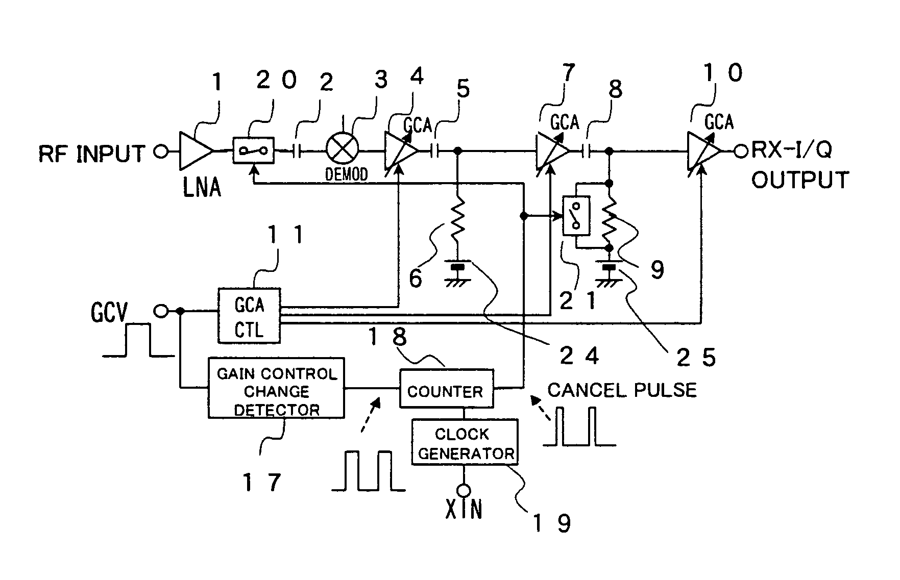
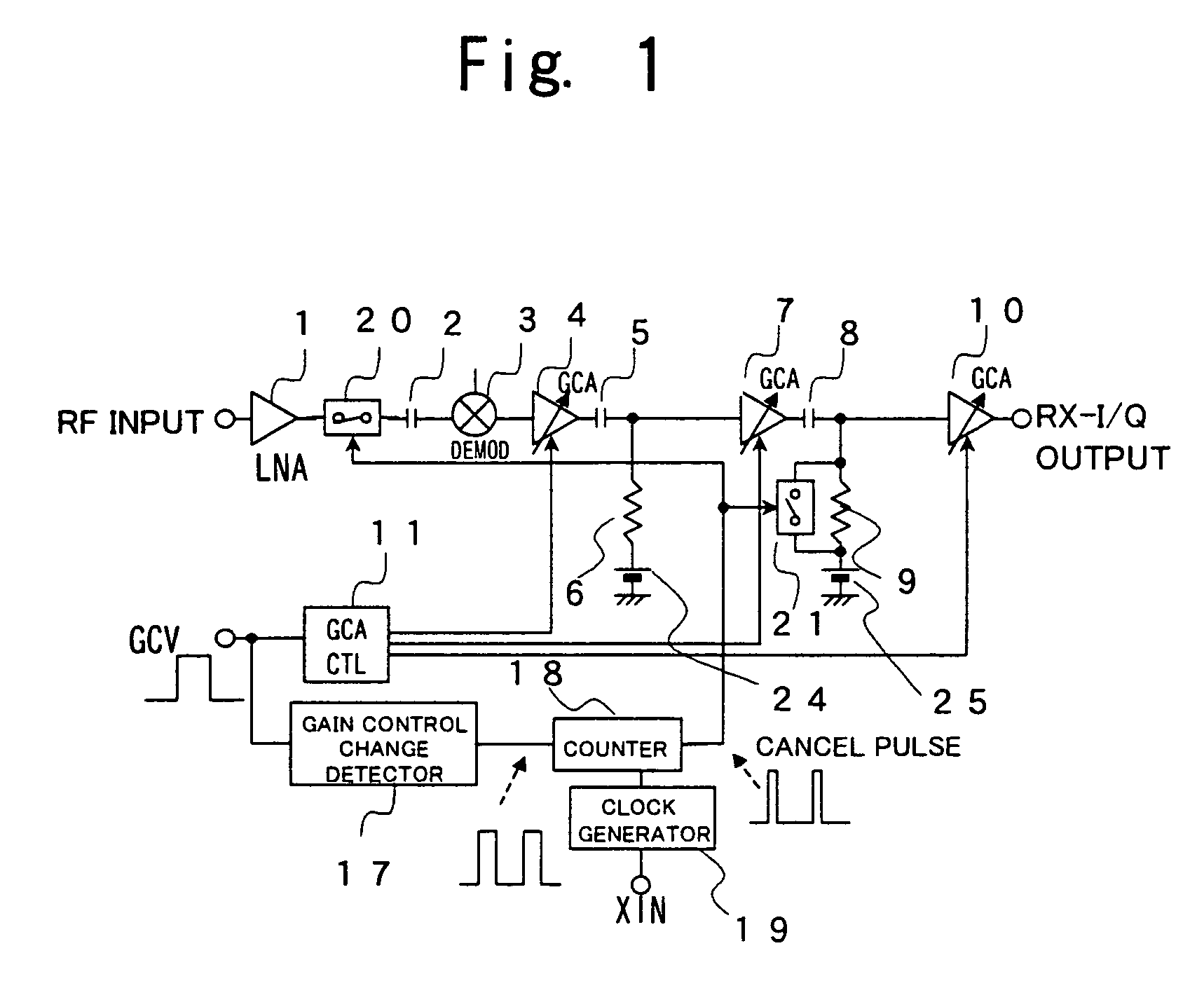
[0038]FIG. 1 is a block diagram which shows the structure of a DC-offset transient response cancel system according to a first embodiment of the present invention. In FIG. 1, denoted at 17 is a gain control signal change detector. Denoted at 18 is a counter which generates a cancel pulse which has a certain width after the gain control signal change detector 17 has detected a change of a gain control signal. Denoted at 19 is a clock generator which generates clocks which are to be used by the counter 18 from a reference signal XIN. Denoted at 20 is a first switch which turns on and off in accordance with the high level and the low level of the cancel pulse for the purpose of blocking an AC signal. Denoted at 21 is a second switch which turns on and off at the same timing as the switch 20, in order to short a resistor 9.

[0039]A low noise amplifier 1, a second capacitor 2, a demodulator 3, a first GCA 4, a second capacitor 5, a first resistor 6, a second GCA 7,...


PUM


Abstract

A high pass filter is disposed to an output part of a gain control amplifier. A gain control signal change detector detects a change of a gain control signal from the gain control amplifier. Upon detection of a change of the gain control signal, a counter and a clock generator generate a cancel pulse which has a certain width, and using the cancel pulse, a first switch cuts an AC signal which is fed to the gain control amplifier. Further, using the same cancel pulse, a second switch reduces the time constant of the high pass filter. Through this operation, a transient response of a DC offset is eliminated.

Description

BACKGROUND OF THE INVENTION[0001]1. Field of the Invention[0002]The present invention relates to a DC-offset transient response cancel system which cancels out a transient response of a DC offset which deteriorates the voice quality in a direct conversion system, i.e., a system which will be the mainstream system in the future for mobile telephones. A transient response of a DC offset worsens a bit error rate and makes it impossible to correctly decode a transmitted signal.[0003]2. Background Art[0004]Over the recent years, more and more mobile telephone systems are shifting from heterodoxy conversion systems to direct conversion systems which operate at low power and are advantageous to size reduction. However, a direct conversion system has a problem of a DC offset from which a heterodoxy conversion system is free.[0005]A prior art on direct conversion systems will now be described.[0006]FIG. 4 is a block diagram which shows the prior art on a direct conversion system. In FIG. 4, ...

Claims


Application Information

Patent Timeline
Patent Type & Authority Patents(United States)
IPC IPC(8): G01R25/00H03G3/02H03G3/10H04B1/30
CPCH04B1/30
Inventor OHTANI, YUTAKAKOMORI, HIROSHI
Owner PANASONIC CORP
Why Eureka
Try Eureka