Working position measuring system

a technology of working position and measuring system, which is applied in the direction of wave based measurement system, angle measurement, instruments, etc., can solve the problems of difficult manual operation by the operator, difficult to achieve photodetection or light receiving, and difficult to operate a photodetection unit, etc., to achieve simple and inexpensive manner, high working efficiency

Active Publication Date: 2006-09-19
KK TOPCON
View PDF3 Cites 39 Cited by
  • Summary
  • Abstract
  • Description
  • Claims
  • Application Information

AI Technical Summary

Benefits of technology

[0022]It is an object of the present invention to provide a working position measuring system, which is designed in the same structure for indoor and o

Problems solved by technology

If the photodetection unit is small, it is difficult to operate manually by the operator, and the photodetection unit is designed in larger size.
In the photodetection device with photodetection range of several tens of cm, photodetection or light receiving is difficult to achieve.
However, problem arises in that the phot

Method used


Image

  • Working position measuring system
  • Working position measuring system
  • Working position measuring system

Examples


Embodiment Construction

[0043]Description will be given below on embodiments of the present invention referring to the drawings.

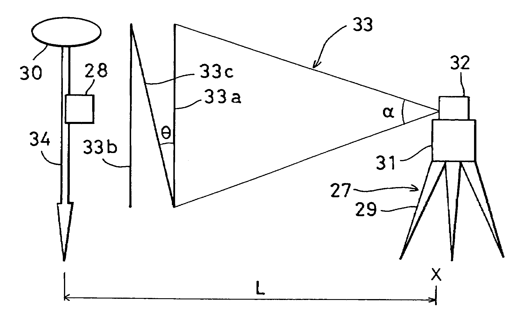
[0044]First, general features of a working position measuring system of the present invention are described referring to FIG. 1.

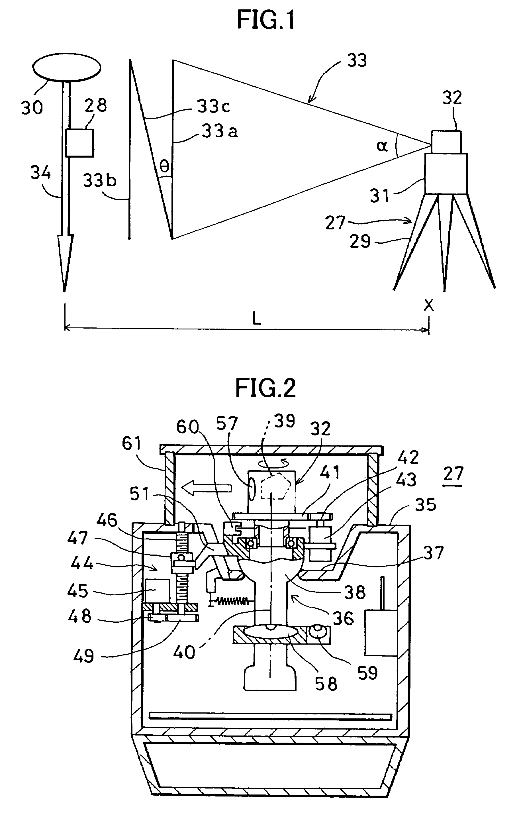
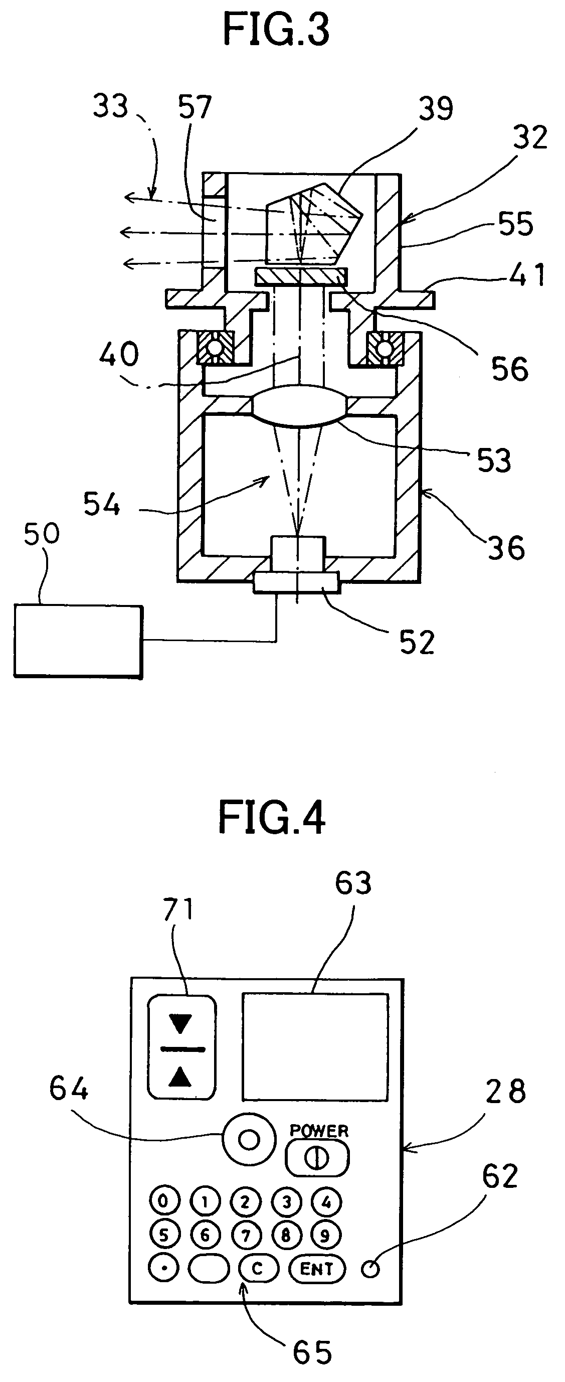
[0045]The working position measuring system primarily comprises a rotary laser device 27 for projecting a fan-shaped beam by rotary irradiation and a photodetection sensor device 28 for receiving the fan-shaped beam.

[0046]A tripod 29 is installed so that the tripod is approximately aligned with a known point X, and the rotary laser device 27 is mounted on the tripod 29. The rotary laser device 27 comprises a main unit 31 and a rotator 32 rotatably mounted on the main unit 31. A laser beam 33 is projected by rotary irradiation from the rotator 32. The photodetection sensor device 28 is supported by a predetermined supporting means. FIG. 1 shows how the device of the present invention is operated in field operation. The photodetection sensor device 28 is in...


PUM


Abstract

A working position measuring system, comprising a rotary laser device for irradiating and rotating a laser beam and a photodetection sensor device for receiving the laser beam and for detecting a working position, wherein the rotary laser device comprises a laser projector for projecting at least two fan-shaped beams with at least one beam tilted, and the photodetection sensor device comprises at least one photodetection unit for receiving the fan-shaped beams and an arithmetic unit for calculating an elevation angle relative to the rotary laser device based on photodetection signals produced when the photodetection unit receives the light beam.

Description

BACKGROUND OF THE INVENTION[0001]The present invention relates to a working position measuring system for projecting a laser beam by rotary irradiation and for measuring a working position from photodetecting condition of the laser beam.[0002]In the past, as a typical device for forming a reference plane by projecting a laser beam by rotary irradiation, a rotary laser device and a photodetection device for receiving the laser beam have been known.[0003]The rotary laser device forms a reference plane by irradiating and rotating a laser beam with a spot-like luminous flux. For instance, by irradiating and rotating the laser beam within a horizontal plane, a horizontal reference plane can be formed. By irradiating and rotating the laser beam within a vertical plane, a vertical reference plane can be formed. By irradiating and rotating the laser beam within a tilted plane, a tilted reference plane can be formed.[0004]The photodetection device comprises a photodetection unit for receivin...

Claims


Application Information

Patent Timeline
IPC IPC(8): G01C1/00G01C1/06G01B11/03G01C15/00G01S5/14G01S5/16
CPCG01C15/002G01S19/43G01S5/16G01S5/0072
Inventor OHTOMO, FUMIOOSARAGI, KAZUKIHAYASHI, KUNIHIRO
Owner KK TOPCON
Why Eureka
Try Eureka