Spectral imaging for vertical sectioning

a technology of vertical sectioning and spectral imaging, which is applied in the field of optical microscopy, can solve problems such as spectral oscillations or “fringes” in the emission spectrum, and achieve the effect of effective scanning the vertical distribution

Inactive Publication Date: 2006-09-19
TRUSTEES OF BOSTON UNIV
View PDF8 Cites 33 Cited by
  • Summary
  • Abstract
  • Description
  • Claims
  • Application Information

AI Technical Summary

Benefits of technology

[0011]The spectral self-interference fluorescent microscopy technique is combined with variable standing wave illumination to allow the height determination capability of spectral self-interference fluorescent microscopy to be applied to an arbitrary vertical distribution of fluorescent samples. The variable standing wave illumination technique employed by the presently disclosed invention comprises configuring the first reflecting surface to reflect emission wavelengths and be transparent at an excitation wavelength, and providing a movable wavelength-independent reflecting surface configured to reflect the excitation wavelength. Excitation light is then provided by a light source and directed to the movable reflecting surface along a vertical axis, and the direct excitation light and the light reflected by the movable surface interfere to form at least one standing wave aligned in the direction of the vertical axis. Next, the movable reflecting surface is moved to translate the standing wave, thereby effectively scanning the vertical distribution of fluorescent samples through the standing wave. Such scanning causes fluorophores to emit light within a plurality of thin sections of the sample distribution orthogonal to the vertical axis.

Problems solved by technology

The direct and reflected light undergo constructive and destructive interference, thereby causing spectral oscillations or “fringes” in the emission spectrum.
The direct and reflected light associated with each sample section undergo constructive and destructive interference to cause fringes in the corresponding emission spectrum.

Method used


Image

  • Spectral imaging for vertical sectioning
  • Spectral imaging for vertical sectioning
  • Spectral imaging for vertical sectioning

Examples


Embodiment Construction

[0025]U.S. Provisional Patent Application No. 60 / 256,574 filed Dec. 19, 2000 is incorporated herein by reference.

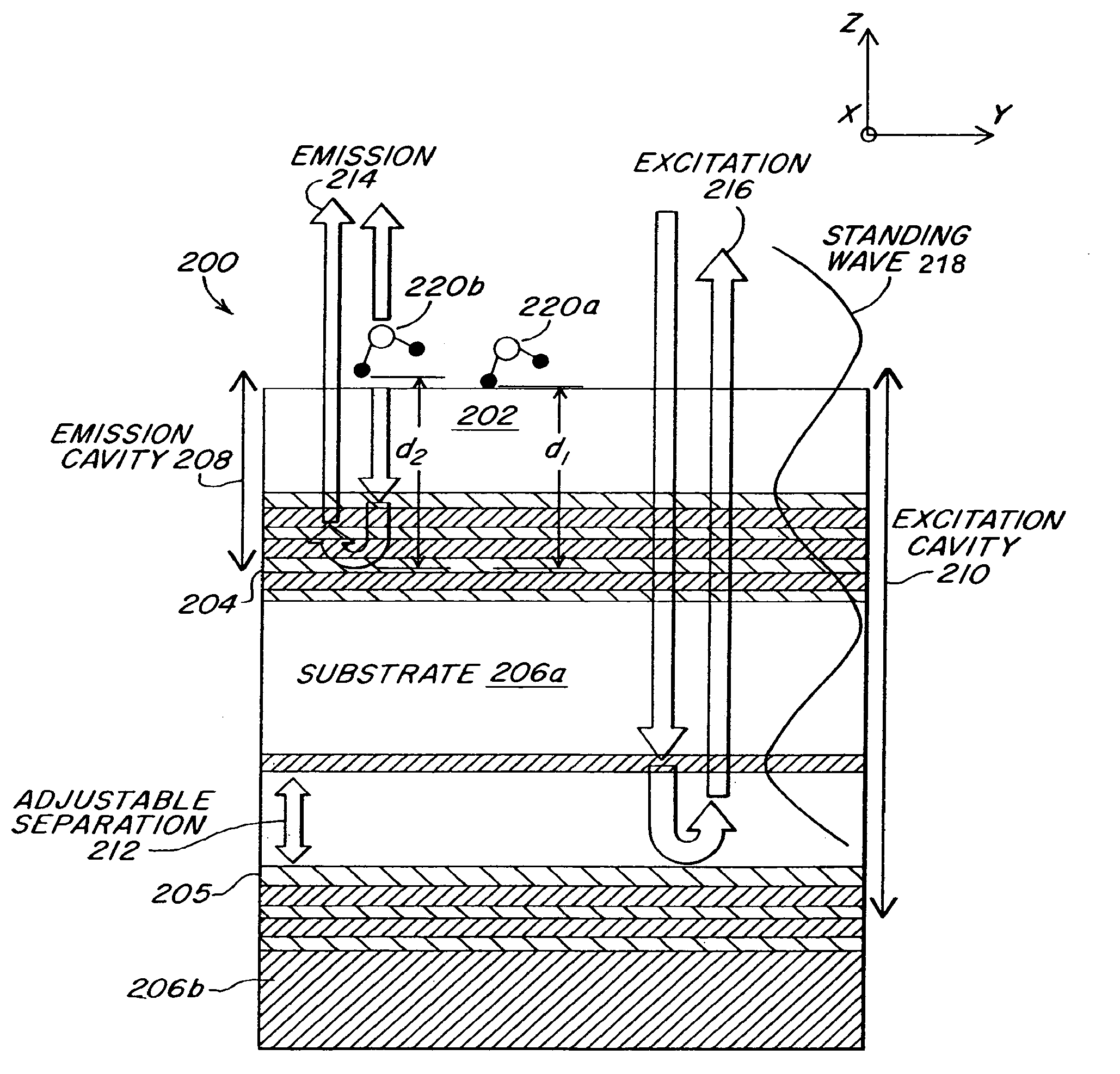
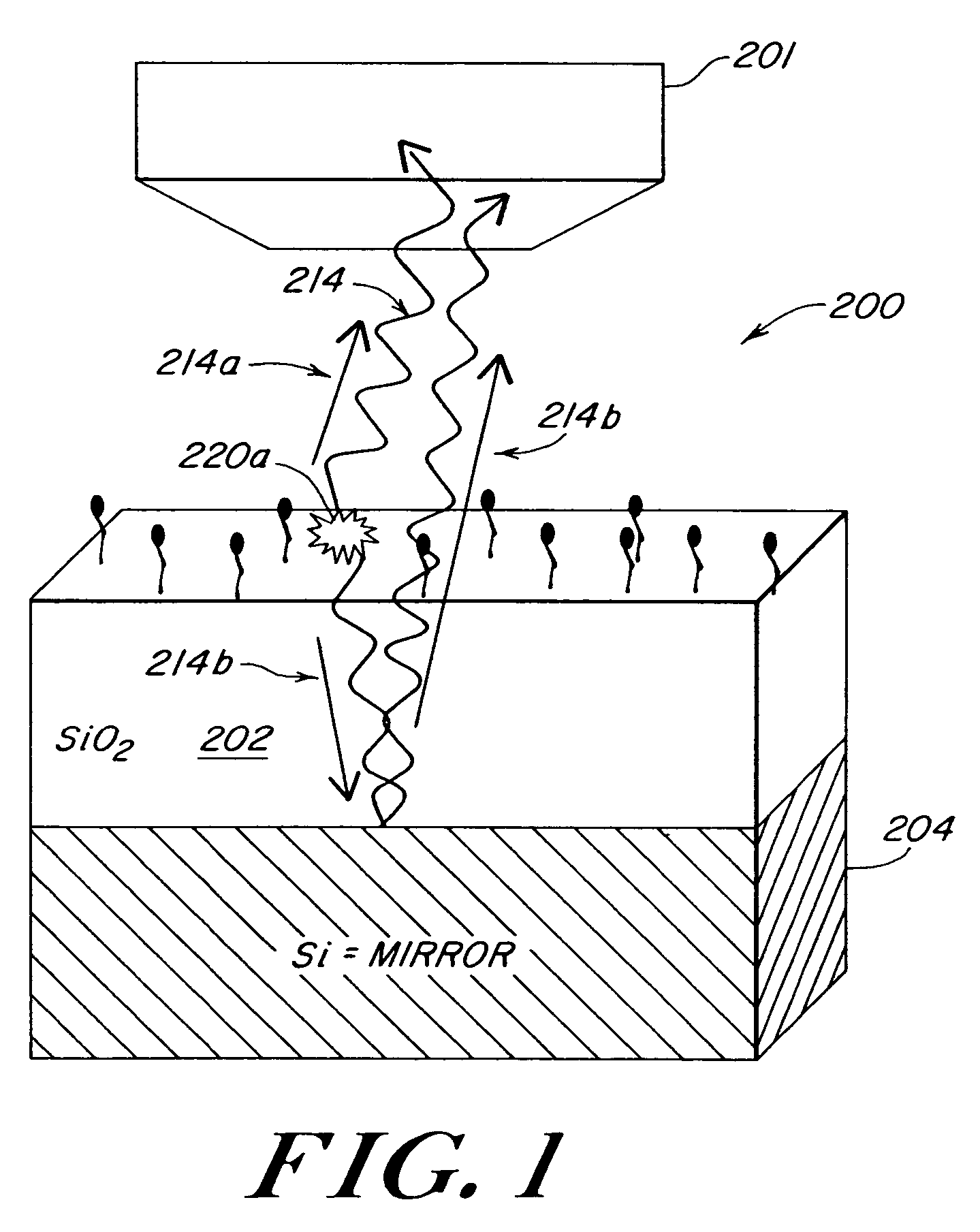
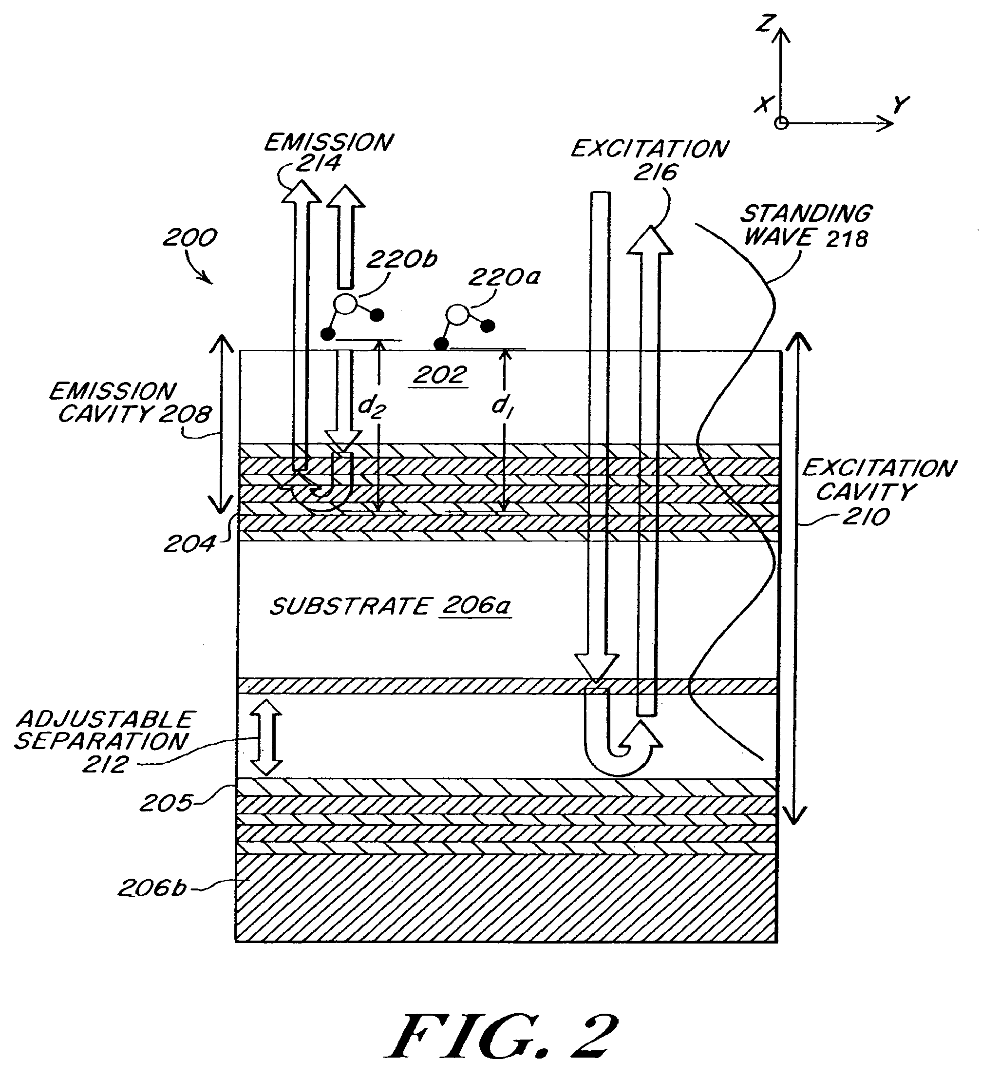
[0026]A method and apparatus for performing three-dimensional (3-D) optical microscopy with nano-meter scale resolution is provided. Such high resolution 3-D optical microscopy is achieved by employing spectral self-interference fluorescent microscopy to determine an optical path length between at least one fluorescent microscopy sample and a reflecting surface, employing variable standing wave illumination to extend the capabilities of the spectral self-interference fluorescent microscopy technique to provide vertical sectioning of an arbitrary distribution of fluorescent samples, and employing rotating aperture interferometric nanoscopy to provide such sectioning along a plurality of axes to generate image information suitable for reconstructing the three-dimensional structure of the sample distribution.

[0027]The presently disclosed 3-D optical microscopy apparatus empl...


PUM


Abstract

A method and apparatus for performing optical microscopy in one to three dimensions employs a spectral self-interference fluorescent microscopy technique that includes providing at least one fluorescent microscopy sample, at least one objective lens, and at least one reflecting surface. The fluorescent sample is disposed between the objective lens and the reflecting surface, the distance from the sample to the reflecting surface being several to several tens times an excitation wavelength. Excitation light causes the fluorescent sample to emit light, at least a portion of which is reflected by the reflecting surface. The objective lens collects the reflected light and the light emitted directly by the fluorescent sample. The direct and reflected light interfere causing spectral oscillations in the emission spectrum. The periodicity and the peak wavelengths of the emission spectrum are spectroscopically analyzed to determine the optical path length between the fluorescent sample and the reflecting surface.

Description

CROSS REFERENCE TO RELATED APPLICATIONS[0001]This application claims priority of U.S. Provisional Patent Application No. 60 / 256,574 filed Dec. 19, 2000 entitled SPECTRAL IMAGING FOR VERTICAL SECTIONING.STATEMENT REGARDING FEDERALLY SPONSORED RESEARCH OR DEVELOPMENT[0002]This invention was made with Government Support under Contract Number DBI-9812377 awarded by the National Science Foundation, Contract Number 99-35201-8435 awarded by the U.S. Department of Agriculture and Contract Number JPL-1213572 awarded by DARPA. The Government has certain rights in the invention.BACKGROUND OF THE INVENTION[0003]The present invention relates generally to optical microscopy, and more specifically to optical microscopy in one to three dimensions that provides increased resolution while enhancing the specificity of optical measurements.[0004]Techniques for performing optical microscopy are known that are capable of providing high resolution three-dimensional (3-D) imaging. Such optical microscopy t...

Claims


Application Information

Patent Timeline
Patent Type & Authority Patents(United States)
IPC IPC(8): G01B9/02G02B21/22
CPCG01B9/04G01N21/6458G01B9/02023G02B21/22G01B9/02044G01N21/4795G01N2021/6441G01N2021/6417
Inventor UNLU, SELIM M.SWAN, ANNAGOLDBERG, BENNETT B.IPPOLITO, STEPHENMOISEEV, LEVLIPOLF, SAMUELTONG, YUNJIE
Owner TRUSTEES OF BOSTON UNIV
Why Eureka
Try Eureka