
Method and apparatus for obtaining geometrical data relating to a canal

a technology of geometrical data and geometrical data, which is applied in the direction of diagnostics, catheters, sensors, etc., can solve the problems of not solving the problems relating to the usual way of producing shells as described, no satisfactory solutions presented, and the probe is mounted on a stiff rod

Inactive Publication Date: 2006-09-19
OTICON
View PDF8 Cites 44 Cited by
  • Summary
  • Abstract
  • Description
  • Claims
  • Application Information

AI Technical Summary

Benefits of technology

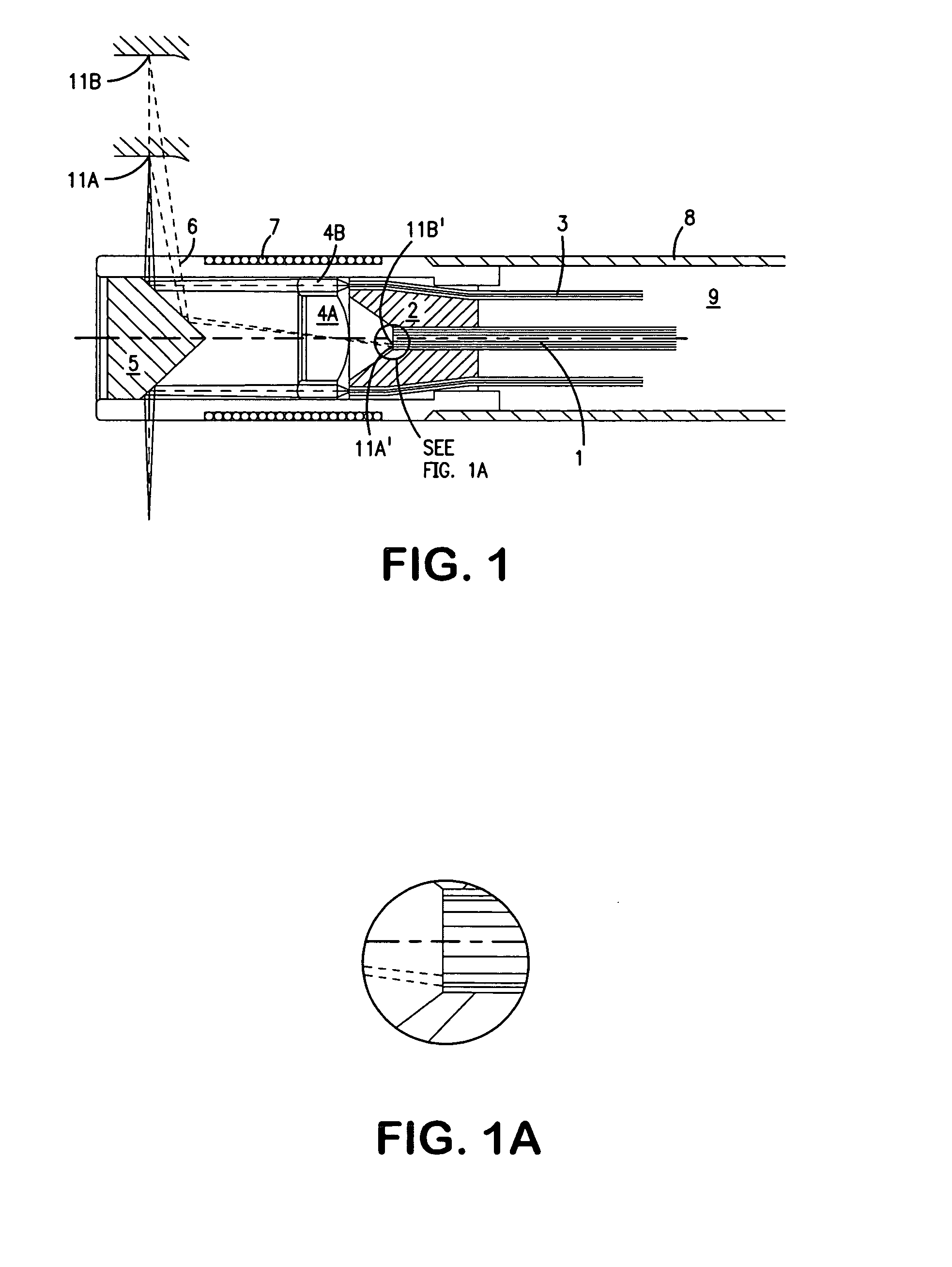
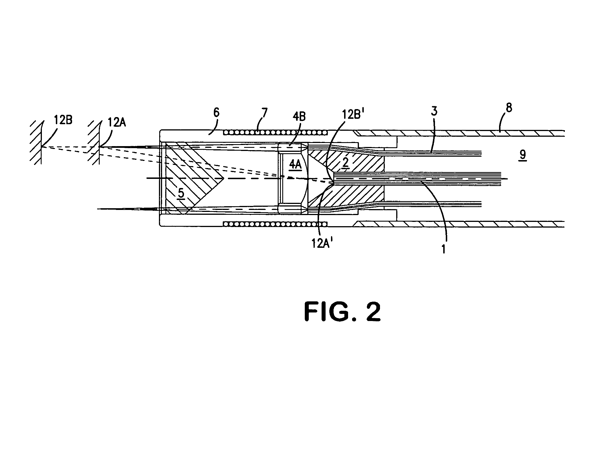
[0019]The object of the invention is to provide a method for obtaining geometrical data relating to the internal surface of a canal in order to be able to generate an exact model of the internal surface of the canal. It is an important aspect of the present invention, that during the measurement a bottom wall of the canal is not touched. This is achieved by the method according to claim 1. The invention uses light to determine the distance from the tip of a probe to the internal wall of the canal, and based on the position of the probe, this information is used to generate information about the shape of the canal. Light with a first and a second wavelength range is directed onto a partially reflective and partially transparent surface at the distal portion of the probe. Light in the first wavelength range is reflected from the surface to illuminate at least one point of a circumferential area of the internal surface of the canal, and light in the second wavelength range is transmitted through the surface to illuminate an area in front of the distal portion of the probe. The light reflected from the illuminated areas is received and directed to at least one light sensitive element to generate an output relating to the first and the second wavelength range. The output relating to the first wavelength range is analyzed to determine the distance from the probe to the internal surface of the canal at points of the circumference, and the output relating to the second wavelength range is analyzed to determine the distance from the probe to an object in front of the probe. Thereby it is ensured that the bottom surface of the canal is not touched or injured while the internal surface of the canal is measured. By the use of light to determine the distance between the probe and the surface of the canal, it is easy to locate foreign object in the canal such as hair or earwax, and these objects are left out of the data model. In this way a more precise model is obtained. Further the use of light makes it possible to obtain very precise data, without touching any internal wall part of the canal.
[0021]In an embodiment of the method distance data are obtained and recorded while position data concerning the spatial position and rotation of the distal portion of the probe are obtained and recorded during movement of the probe from a first to a second location. Thereby an operator may map a larger coherent area of the internal surface of the canal in an easy and straightforward way as the data are recorded during operator controlled motion of the probe.
[0025]In an embodiment of the invention the position data are obtained using transdusing means transmitting a magnetic field associated with the distal portion of the probe and second transdusing means detecting the magnetic field generated by the transmitter fixed relative to the head of the patient. The use of this method of obtaining the position data is very precise. Further it is possible to make the measurement noise insensitive. Also the transmitter of the magnetic field may be made small, so that it may easily be build into the tip of the probe.

Problems solved by technology

In the following documents some of the above problems are addressed, but no satisfactory solutions are presented.
The document further discloses a method for tracking the ear canal based on the use of an ear impression, but such a method would not resolve the problems relating to the usual way of producing shells as described above.
The probe is mounted on a stiff rod, and is not capable of following the possible bends of the ear canal.
This limits the use of the probe, as many people especially older people have ear canals with sharp bends.
Various methods and apparatuses for determining the internal properties of internal surfaces have been suggested, however none of these are useful when it comes to mapping the internal surface of a canal of the human body, in order to generate a digital model of the interior wall of the canal.

Method used


Image

  • Method and apparatus for obtaining geometrical data relating to a canal
  • Method and apparatus for obtaining geometrical data relating to a canal
  • Method and apparatus for obtaining geometrical data relating to a canal

Examples


Embodiment Construction

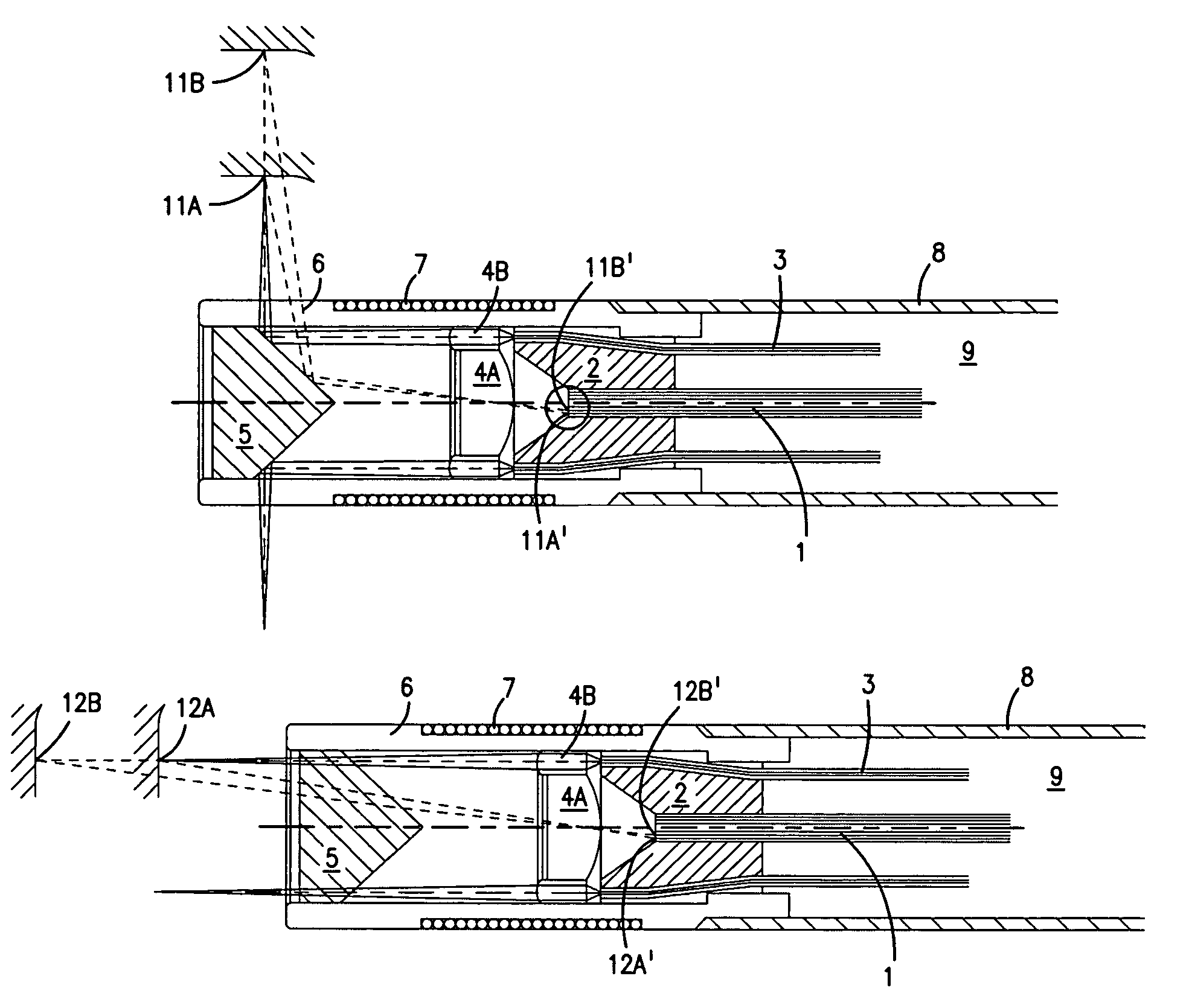
[0048]The probe shown in FIG. 1 has a distal light emitting portion and a rod portion 9 connecting the distal portion to a proximal part (not shown). The rod portion 9 comprises a flexible pipe 8 and a set of light guides 3 and an image guide 1. The image guide 1 is placed centrally in the pipe 8, and the light guides 3 are arranged between the pipe 8 and the image guide 1. Near the tip of the probe the light guides 3 are fastened between an inner bushing 2 and an outer tube 6. An annular lens 4B is arranged at the bushing 2 to capture the light emitting from the light guides 3, in order to focus said light. The focused light beam is directed to a first portion of a mirror 5 mounted at the tip of the tube 6. The first portion of the mirror 5 has a circumferential conical plane with a top angle of 45°. Thereby the focused light beam emitted from the lens 4B will be directed in a right angel away from the longitudinal axis of the probe, and towards a surrounding canal wall 11. The tip...


PUM


Abstract

The invention uses light to determine the distance from the tip of a probe to the internal wall of the canal, and based on the position of the probe, this information is used to generate information about the shape of the canal. Light with a first and a second wavelength range is directed onto a semi-transparent mirror surface at the distal portion of the probe. Light in the first wavelength range is reflected from the mirror surface to illuminate a circumferential area of the internal surface of the canal, and light in the second wavelength range is transmitted through the mirror surface to illuminate an area in front of the distal portion of the probe. The received light is analyzed in the first wavelength range to determine the distance from the probe to the internal surface of the canal at points of the circumference, and analyzed in the second wavelength range to determine the distance from the probe to an object in front of the probe. Thereby it is ensured, that the bottom surface of the canal is not touched or injured while the internal surface of the canal is measured.

Description

AREA OF THE INVENTION[0001]The invention relates to a method and an apparatus for obtaining geometrical data relating to the internal surface of a canal. The method and the apparatus are used to gain a data mapping of the internal surface of a canal, so that a 3-dimensional data or digital model of the internal surface of the canal is obtained. In some cases it is important to also obtain information about a bottom surface of the canal. This is especially important when the canal forms part of the human body. In this case the bottom surface may be sensitive, and should not be touched. Also in connection with inspection and measurement of other canals, which are sensitive to contact such as surfaces of newly painted or otherwise surface treated holes the invention may be used and provides an advantage over the prior art.[0002]If the human ear is mapped using the method, the 3-dimension model can be used to produce a shell, which has the exact shape of the ear canal and the shell may ...

Claims


Application Information

Patent Timeline
Patent Type & Authority Patents(United States)
IPC IPC(8): G01B11/00A61B18/22A61B1/227A61B5/107G01B11/24
CPCA61B1/227G01B11/24A61B5/6817A61B5/1076
Inventor JENSEN, PREBEN DAMGARDOLESEN, TOM
Owner OTICON
Learn More