Radio apparatus, method for receiving its signal, method for measuring its filter coefficient, and program for measuring its filter coefficient

a radio apparatus and filter coefficient technology, applied in the field of radio apparatuses and their signal reception methods and filter coefficient measurement methods and programs, can solve problems such as difficulty in matching the characteristics of analog rf circuits

Inactive Publication Date: 2006-09-19
GK BRIDGE 1
View PDF21 Cites 112 Cited by
  • Summary
  • Abstract
  • Description
  • Claims
  • Application Information

AI Technical Summary

Benefits of technology

[0047]Furthermore in accordance with the present invention a plurality of filter means digitally compensating for a difference of a characteristic between analog circuits can be provided with a filter coefficient accurately determined for example prior to shipment of a radio apparatus under a condition with a frequency offset corrected and a timing of sampling corrected.
[0048]Furthermore in accordance with the present invention a plurality of filter means digitally compensating for a difference of a characteristic between analog circuits can be provided with a filter coefficient accurately determined for example in a shipped radio apparatus by selecting a satisfactory signal received from a mobile terminal and using the selected signal for calculation.

Problems solved by technology

However, because of variations in production, the analog RF circuits, configured of the same amplifiers, the same frequency mixer and the same filters, still provide different frequency characteristics of phase and amplitude and it is difficult to match the characteristics between the analog RF circuits.

Method used


Image

  • Radio apparatus, method for receiving its signal, method for measuring its filter coefficient, and program for measuring its filter coefficient
  • Radio apparatus, method for receiving its signal, method for measuring its filter coefficient, and program for measuring its filter coefficient
  • Radio apparatus, method for receiving its signal, method for measuring its filter coefficient, and program for measuring its filter coefficient

Examples


first embodiment

[0066

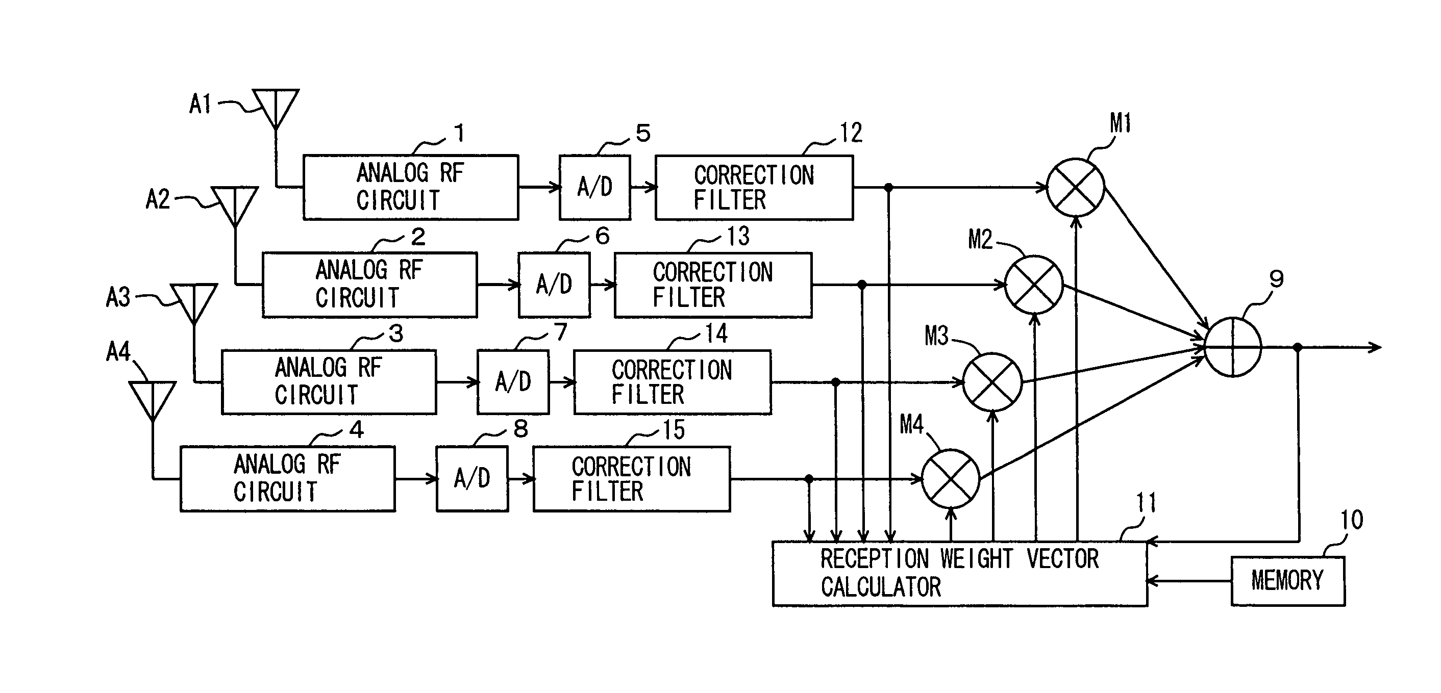
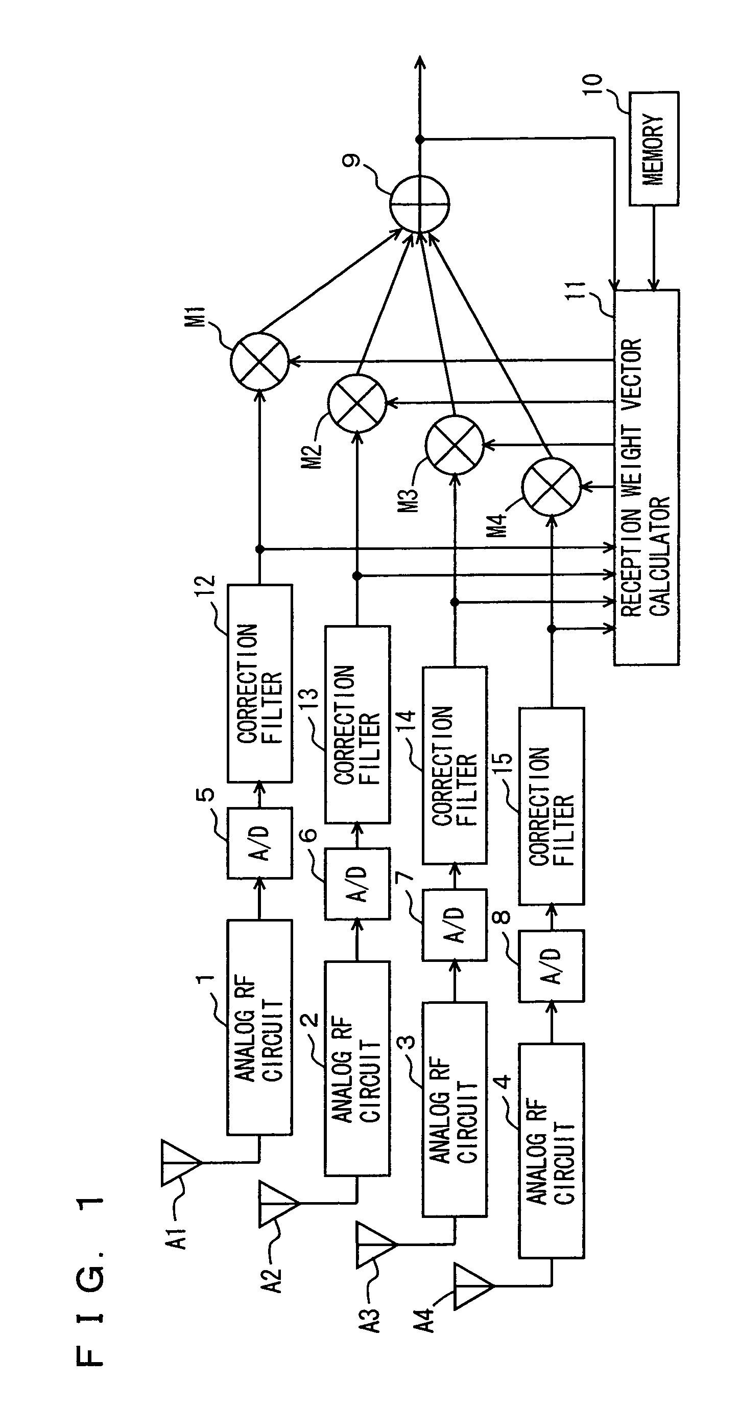
[0067]FIG. 1 is a functional block diagram representing a configuration of a system of a radio base station in accordance with the present invention in a first embodiment, in particular for illustrating functionally a processing effected by a DSP of a radio station by software.

[0068]The configuration of the radio base station shown in FIG. 1 is identical to that of the conventional radio base station shown in FIG. 17, except the following:

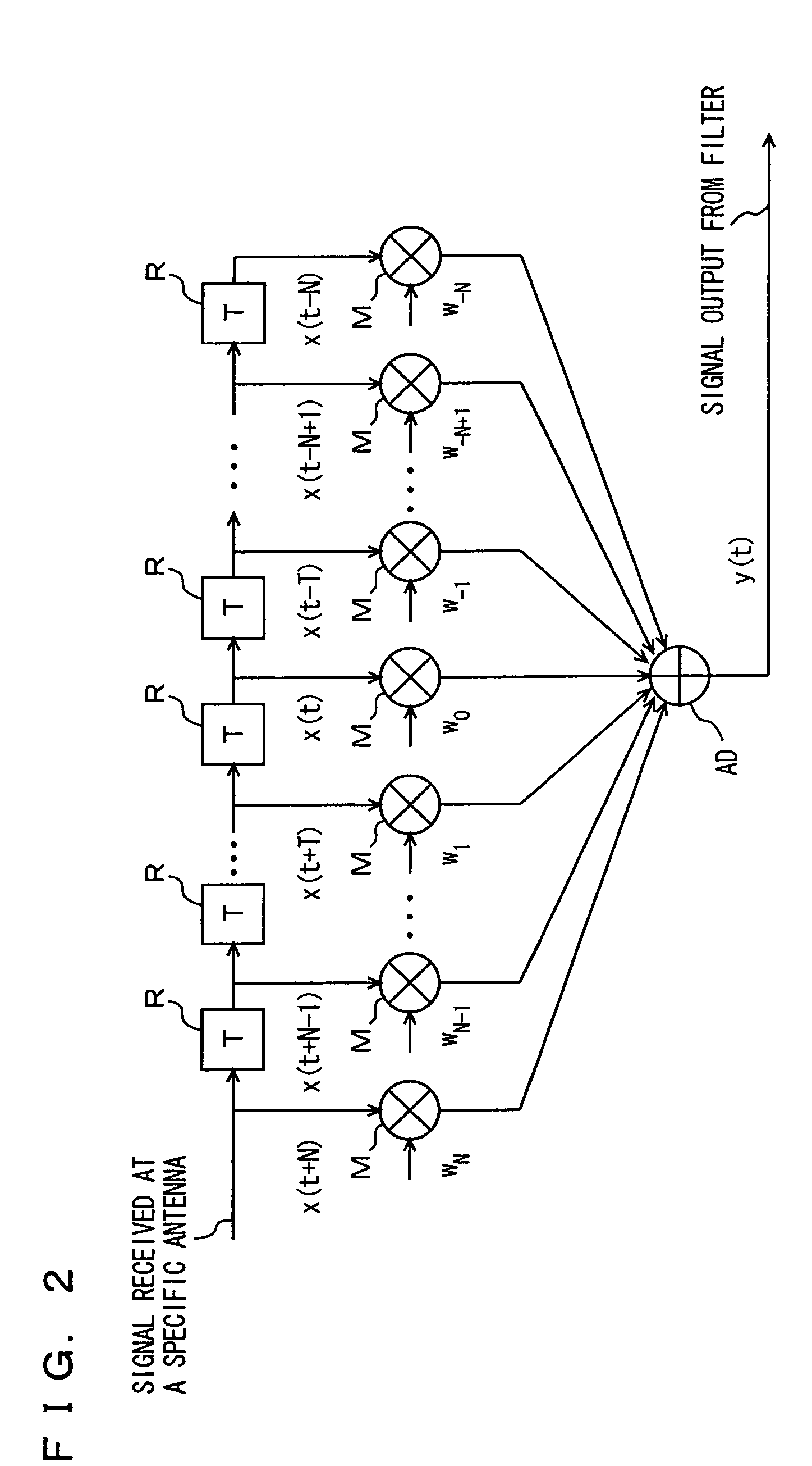
[0069]At a stage subsequent to A / D converters 5–8 and preceding adaptive array processing provided by the DSP (not shown) there are inserted correction filters 12–15 each configured of a digital filter.

[0070]Correction filters 12–15 are each a digital filter having a characteristic (a filter coefficient, i.e., a tap coefficient) compensating for a difference between a circuit characteristic (e.g., frequency characteristic of phase and amplitude) of a corresponding one of analog RF circuits 1–4 and a predetermined, ideal circuit characteristic....

second embodiment

[0083

[0084]The filter coefficients (tap coefficients) of correction filters 12–15 used in the radio base station of the first embodiment are measured (determined), as described hereinafter.

[0085]The filter coefficient can be measured in a factory before shipment of the radio station or automatically measured in the shipped radio base station in operation.

[0086]Initially as the second embodiment a filter coefficient measurement effected before shipment of the radio base station will be described.

[0087]FIG. 4 is a schematic block diagram showing a configuration of a system in the second embodiment for measuring a filter coefficient before the radio base station is shipped.

[0088]With reference to FIG. 4, to measure a filter coefficient before shipment, a signal generator (SG) 40 generates a burst modulation signal and a 4-distributor 50 distributes the generated burst modulation signal to four which are in turn fed through cables, respectively, to a radio base station 20 at four antenn...

third embodiment

[0119

[0120]As has been described above, filter coefficients can be measured in a radio base station having been shipped from a factory and in operation. More specifically, even if before shipment the method described in the second embodiment is employed to measure filter coefficients in the factory precisely, after the installation as an analog RF circuit has its parts altering over years and the environment also changes, an error of a characteristic between signal streams can change. Accordingly, it is necessary to re-measure filter coefficients (tap coefficients) of a correction filter of the base station regularly at intervals corresponding to a period of time (once a year for example).

[0121]FIG. 7 is a schematic block diagram showing a configuration in the third embodiment for measurement of a filter coefficient after the radio base station is shipped.

[0122]With reference to FIG. 7, after the shipment it is impossible that control PC30 and SG40 are prepared and by a signal of a ...


PUM


Abstract

Corresponding to antennas analog RF circuits are provided and their outputs are converted by A/D converters to digital signals. Subsequent thereto and preceding an adaptive array processing, correction filters are arranged. Each correction filter has a filter coefficient for compensating for a difference between a characteristic of an analog RF circuit corresponding thereto and an ideal circuit characteristic. Thus an error of a characteristic between the analog RF circuits can be compensated for. The series of operations are implemented by software.

Description

TECHNICAL FIELD[0001]The present invention relates generally to radio apparatuses and their signal reception methods and filter coefficient measurement methods and programs, and particularly to those digitally compensating for an error of a characteristic of analog circuits.BACKGROUND ART[0002]In recent years in a rapidly developing mobile communication system (the Personal Handyphone System (PHS) for example) there has been proposed a system in which when a radio base station and a mobile terminal device communicate, the radio base station employs adaptive array processing to extract a signal received from a specific, desired mobile terminal device.[0003]Adaptive array processing is a processing which calculates from a signal received from a mobile terminal device a weight vector formed of reception coefficients (weights) for respective antennas of the radio base station and provides adaptive control to accurately extract a signal received from a specific mobile terminal device.[00...

Claims


Application Information

Patent Timeline
Patent Type & Authority Patents(United States)
IPC IPC(8): H04M1/00H04B1/00H01Q3/26H03H17/02H04B1/10H04B7/08H04B7/26
CPCH04B7/0848H01Q3/2605
Inventor DOI, YOSHIHARU
Owner GK BRIDGE 1
Why Eureka
Try Eureka