Packet routing system and method

a packet routing and packet technology, applied in the field of packet routing system and method, can solve the problems of affecting the service provider, and posing a host of potentially disastrous consequences for the service provider, and reducing the service pri

Inactive Publication Date: 2006-09-19
FORTINET
View PDF7 Cites 199 Cited by
  • Summary
  • Abstract
  • Description
  • Claims
  • Application Information

AI Technical Summary

Benefits of technology

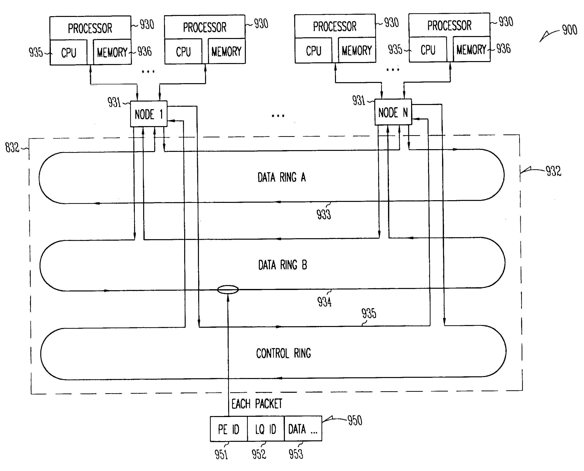
[0017]The present invention provides a flexible, scalable hardware and software platform that allows a service provider to easily provide internet services, virtual private network services, firewall services, etc., to a plurality of customers. This solution can be changes to provision each customer with more or less processing power and storage, according to individual changing needs. a packet routing system includes a processor identifier as part of each packet to route the packets to a physical processor, and a logical queue identifier to route the packets to the destination object within that processor.

Problems solved by technology

The service provider game has grown extremely crowded and fiercely competitive, with numerous players offering similar products and services.
While having a large number of comparable services is arguably beneficial to the enterprise, it poses a host of potentially disastrous consequences for a service provider.
Jockeying for the cost-leader position rapidly drives down service pricing, reducing margins to rubble and rendering the service a commodity.
Furthermore, numerous offerings that are similar in attributes and cost make it very difficult to lock in customers.
Operational costs also present a significant challenge to service providers.
Cumbersome, manual provisioning processes are the primary culprits.
This is a slow and expensive process that cuts into margins and forces significant up-front charges to be imposed on the customer.
Traditional methods of data network service creation, deployment, and management present significant challenges to accomplishing these goals, calling for a new network service model to be implemented.
Enterprise networks are no longer segregated from the outside world; IT managers are facing mounting pressure to connect disparate business units, satellite sites, business partners, and suppliers to their corporate network, and then to the Internet.
This raises a multitude of security concerns that are often beyond the core competencies of enterprise IT departments.
To compound the problem, skilled IT talent is an extremely scarce resource.
While IT managers clearly see the value in utilizing managed network services, there are still barriers to adoption.
Perhaps the most significant of these is the fear of losing control of the network to the service provider.
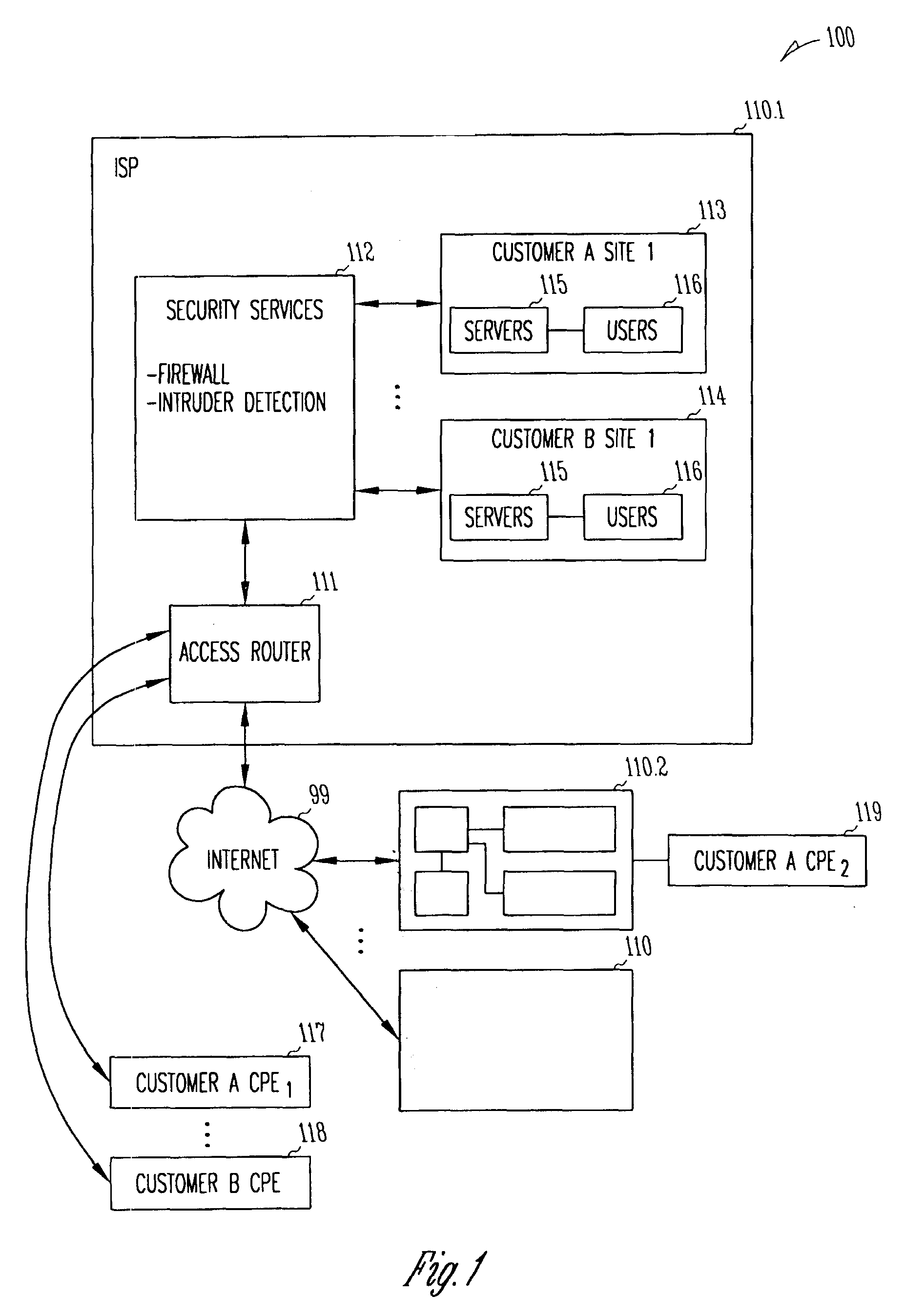
In many cases, service providers and enterprise customers find it too expensive and cumbersome to deploy CPE-based security at every site, but rather deploy secure Internet access points at one or two of the largest corporate sites.
In this model, all remote site Internet traffic is backhauled across the WAN to the secure access point and then out onto the Internet, resulting in increased traffic on the corporate network and performance sacrifices.
Service providers face significant challenges when deploying, managing and maintaining CPE-based managed firewall services.
When a customer expresses interest in utilizing such a service, a consultation with experienced security professionals is required to understand the corporate network infrastructure and site-specific security requirements, yielding a complex set of security policies.
This complex process begins with physical integration of the CPE device into the customer network.
Server-based CPE services, however, require the additional time-consuming step of loading the system OS and software feature sets, adding a further degree of complexity.
Additionally, maintenance processes and costs for CPE-based managed firewall services can also be overwhelming to both the service provider and enterprise customers.
Enterprises are forced to either keep cold spares onsite or be faced with periods of absent security when their firewall fails, a situation that is unacceptable to most of today's information intensive corporations.
Troubleshooting thousands of CPE devices that have been deployed at customer sites is an extremely formidable challenge, requiring extensive call center support resources, as well technicians that can be quickly deployed onsite.
As CPE-based firewall services have traditionally been deployed in private enterprise networks, the original management systems for these devices have difficulty scaling up to manage several large, multi-site service provider customers.
The CPE-based managed firewall model faces service providers with another issue: capital costs.
In addition to the significant costs required to build out a POP / access infrastructure, including multiplexers and high-capacity access routers, the service provider must also assume the initial costs of the CPE device, including firewall and VPN software licensing charges.
This creates steep up-front costs that, coupled with per-site installation charges, can present a serious barrier to service adoption.
The CPE-based model is also limited when rolling out services beyond the managed firewall offering.
This results in higher capital costs, as well as another expensive truck roll.

Method used


Image

  • Packet routing system and method
  • Packet routing system and method
  • Packet routing system and method

Examples


Embodiment Construction

[0036]In the following detailed description of the preferred embodiments, reference is made to the accompanying drawings that form a part hereof, and in which are shown by way of illustration specific embodiments in which the invention may be practiced. It is understood that other embodiments may be utilized and structural changes may be made without departing from the scope of the present invention.

[0037]The leading digit(s) of reference numbers appearing in the Figures generally corresponds to the Figure number in which that component is first introduced, such that the same reference number is used throughout to refer to an identical component which appears in multiple Figures. Signals and connections may be referred to by the same reference number or label, and the actual meaning will be clear from its use in the context of the description.

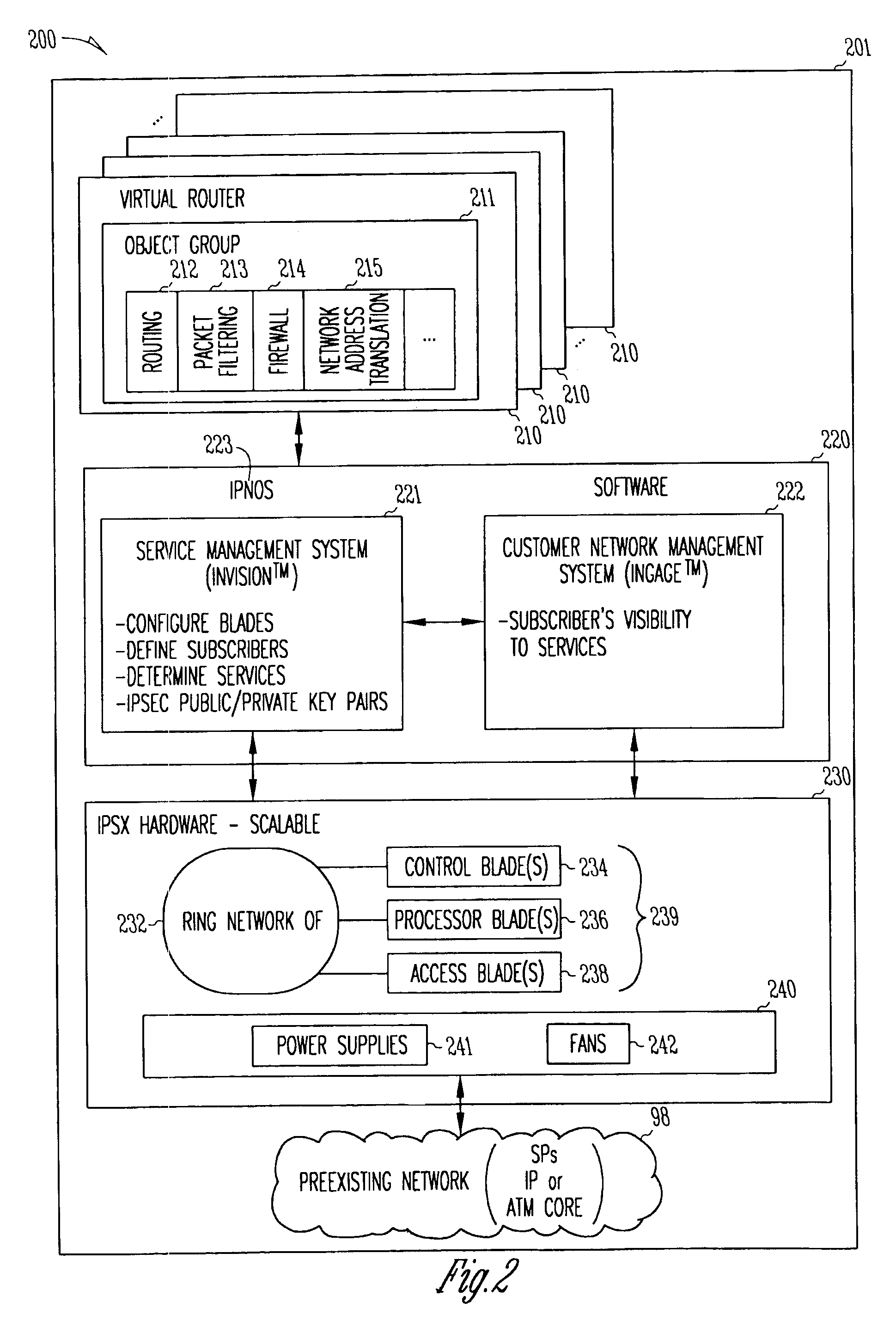
[0038]In some embodiments, the present invention deploys one or more virtual private networks (VPNs) running on one or more carrier-class plat...


PUM


Abstract

A flexible, scalable hardware and software platform that allows a service provider to easily provide internet services, virtual private network services, firewall services, etc., to a plurality of customers. One aspect provides a method and system for delivering security services. This includes connecting a plurality of processors in a ring configuration within a first processing system, establishing a secure connection between the processors in the ring configuration across an internet protocol (IP) connection to a second processing system to form a tunnel, and providing both router services and host services for a customer using the plurality of processors in the ring configuration and using the second processing system. a packet routing system and method is described that includes a processor identifier in each packet to route the packets to a physical processor, and a logical queue identifier to route the packets to the destination object within that processor.

Description

CROSS REFERENCES TO RELATED INVENTIONS[0001]This application is related to a co-pending commonly assigned application titled “SYSTEM AND METHOD FOR DELIVERING SECURITY SERVICES” by inventor Abraham R. Matthews Ser. No. 09 / 661,637 and to two provisional applications each titled “SYSTEMS AND METHOD FOR DELIVERING INTERNETWORKING SERVICES” Ser. No. 60 / 232,577 AND Ser. No. 60 / 232,516 each filed on even date herewith, all incorporated herein by reference.FIELD OF THE INVENTION[0002]This invention relates to the field of internet processors, and more specifically to a method and apparatus of delivering security services such as firewalls.BACKGROUND OF THE INVENTION[0003]The service provider game has grown extremely crowded and fiercely competitive, with numerous players offering similar products and services. While having a large number of comparable services is arguably beneficial to the enterprise, it poses a host of potentially disastrous consequences for a service provider. If all com...

Claims


Application Information

Patent Timeline
Patent Type & Authority Patents(United States)
IPC IPC(8): G06F15/16
CPCH04L12/42H04L45/04H04L63/0272H04L63/1408H04L45/586H04L63/20
Inventor MATTHEWS, ABRAHAM R.WEIR, STEVEN PATRICK
Owner FORTINET
Why Eureka
Try Eureka