
Angular rate sensor

a technology of angular rate sensor and angular rate, which is applied in the direction of acceleration measurement using interia force, turn-sensitive devices, instruments, etc., can solve the problems of inability to produce high volume efficiency in manufacturing process, difficulty in achieving high-volume efficiency, and rapid decrease of sensitivity for detecting coriolis force. , to achieve the effect of high-cost performance, not losing accuracy and simple structur

Active Publication Date: 2006-09-26
SONY CORP
View PDF8 Cites 3 Cited by
  • Summary
  • Abstract
  • Description
  • Claims
  • Application Information

AI Technical Summary

Benefits of technology

The present invention provides an angular rate sensor with high sensitivity, efficiency, and accuracy. The sensor has a simple structure and can be manufactured with high volume efficiency. It includes a quadratic prism-like oscillator formed by laminating a substrate and a piezoelectric material, and detection electrodes that output a signal corresponding to Coriolis force generated in the oscillator. The dimensions of the driving electrode and detection electrodes in the width direction of the oscillator are made different from each other to achieve high accuracy. The sensor can be easily adjusted for driving and detection efficiency to achieve desired sensitivity characteristics.

Problems solved by technology

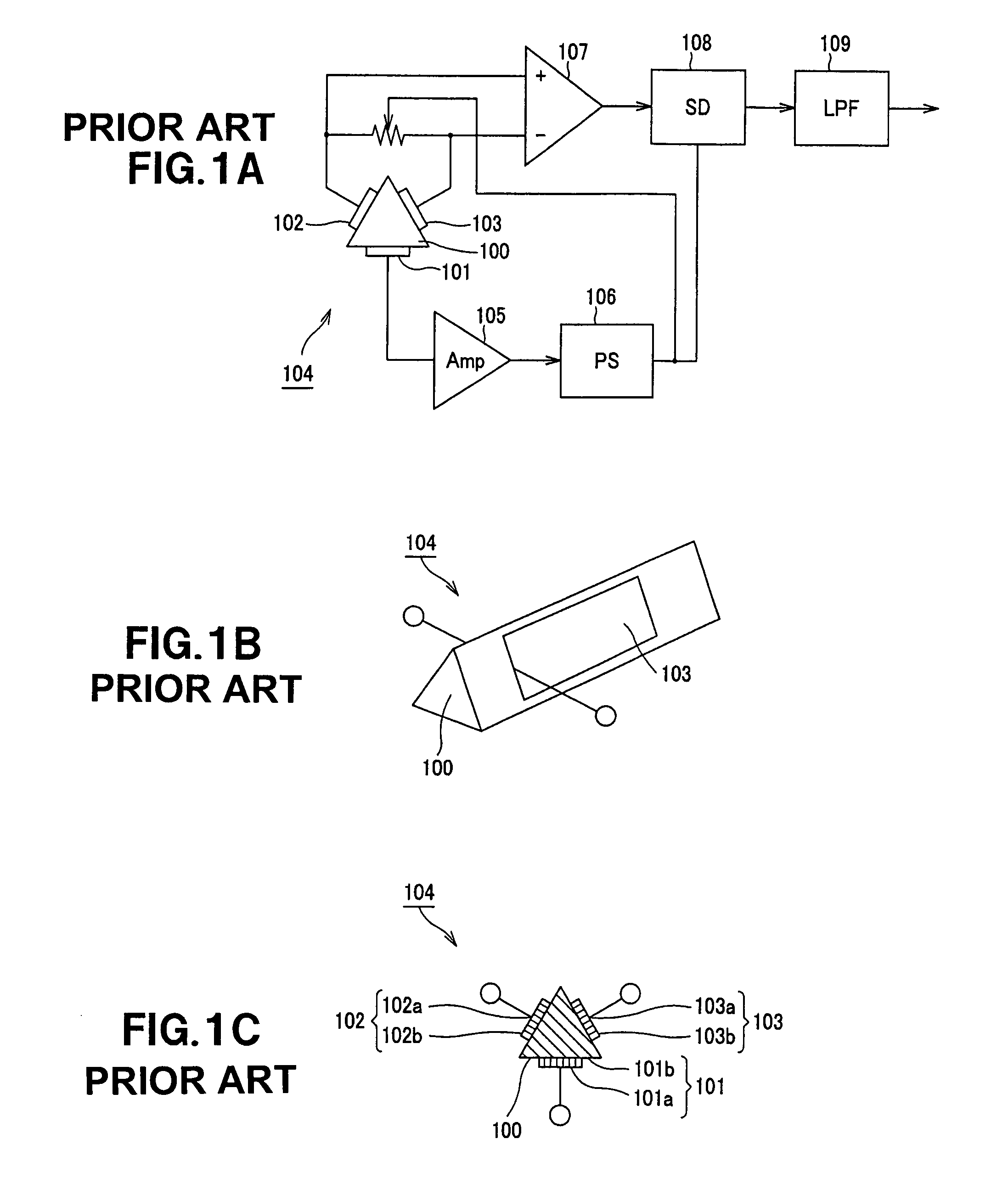
However, the method using a separately-excited oscillation type driving circuit has a problem that when a difference is made between oscillation frequency and resonance frequency of an oscillator due to influence of temperature characteristics of the oscillator or the like, sensitivity for detecting Coriolis force rapidly decreases.
Therefore, the method using a separately-excited oscillation type driving circuit has not been in practical use.
However, the angular rate sensor of this type has a complicated structure, which makes it difficult to produce high volume efficiency in manufacturing process.
For example, in the above configuration, process of bonding piezoelectric elements to each of the triangular prism-like constant elastic oscillators is required, with the result that volume efficiency cannot be improved.
Therefore, manufacturing efficiency is lowered and manufacturing cost is significantly increased.
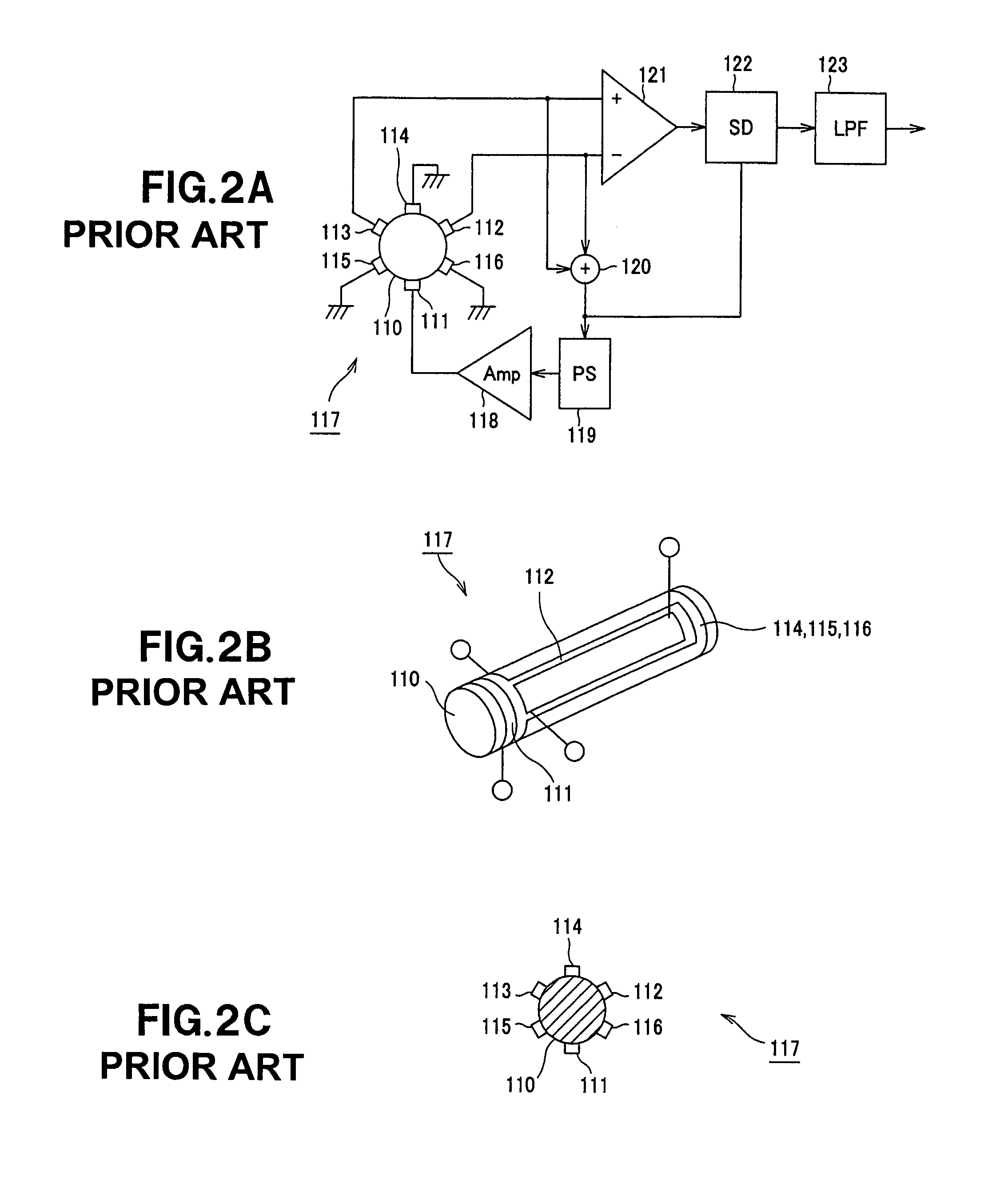
However, in the case where the sensor size is reduced, it is difficult to produce an accurately configured piezoelectric ceramic oscillator 110 and, it is also difficult to print the electrodes onto the piezoelectric ceramic oscillator 110 with high accuracy.
Further, it is not easy to print with high accuracy the electrodes onto the rounded surface of this angular rate sensor.
As described above, the use of the columnar piezoelectric ceramic oscillator 110 makes it difficult to produce the angular rate sensor in large volume.
Even though the mass-production has been realized, it is difficult to reduce manufacturing cost.
Thus, it is difficult to adjust the driving and detection efficiency to desired values at the same time.
That is, the conventional angular rate sensor shown in FIGS. 1A, 1B and 1C has a complicated structure due to the need of bonding the piezoelectric element to the constant elastic metal oscillator, and a complicated oscillator support mechanism.
The conventional angular rate sensor shown in FIGS. 2A, 2B and 2C uses the columnar piezoelectric ceramic oscillator, which makes it difficult to manufacture the oscillator with high accuracy.
Further, it is not easy to print electrodes onto the curved surface accurately.

Method used


Image

  • Angular rate sensor
  • Angular rate sensor
  • Angular rate sensor

Examples


Embodiment Construction

[0036]An embodiment of the present invention will be described below in detail with reference to the accompanying drawings. The present invention is not limited to the following examples, and can be variously modified without departing from the spirit and scope of the invention.

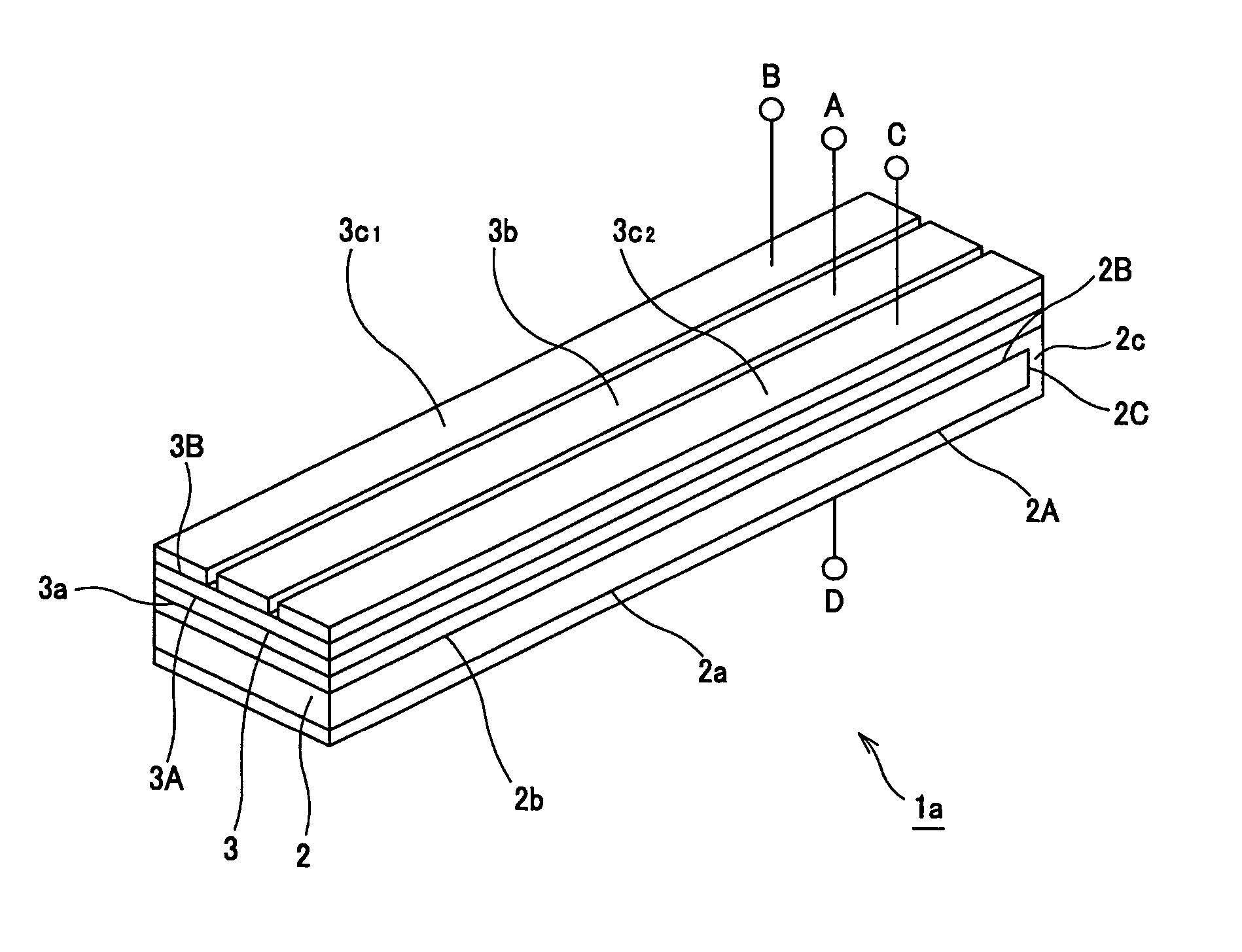
[0037]FIG. 4 is a perspective view showing an oscillator 1a provided in an angular rate sensor 1 to which the present invention is applied. FIG. 5 is a block diagram showing an example of a circuit for realizing the angular rate sensor 1.

[0038]The angular rate sensor 1 according to the present embodiment includes, as shown in FIGS. 4 and 5, the oscillator 1a acting as an oscillation gyro.

[0039]The oscillator 1a is formed by laminating a substrate 2 and a piezoelectric material 3 and formed into a quadratic prism-like shape having a rectangular cross section when the oscillator is cut with a plane perpendicular to the longitudinal direction thereof. The substrate 2 of the oscillator 1a is made of e.g., amorpho...


PUM


Abstract

An angular rate sensor includes: a quadratic prism-like oscillator 1a formed by laminating a substrate 2 and a piezoelectric material 3; a reference electrode 3a which is formed on one main surface 3A of two opposed surfaces of the piezoelectric material 3, the one main surface 3A being bonded to the substrate 2, and which is connected to a reference potential; at least one drive electrode 3b which is formed on the other main surface 3B of the two opposed surfaces of the piezoelectric material 3 in the longitudinal direction of the oscillator 1a, and to which a signal for oscillating the oscillator 1a is supplied; and at least a pair of detection electrodes 3c1 and 3c2 which are formed, in parallel with each other, on the other main surface 3B of the two opposed surfaces of the piezoelectric material 3 in a manner to sandwich the drive electrode 3b, and which output a signal corresponding to Coriolis force generated in the oscillator 1a.

Description

RELATED APPLICATION DATA[0001]The present application claims priority to Japanese Application(s) No(s). P2003-346111 filed Oct. 3, 2003, which application(s) is / are incorporated herein by reference to the extent permitted by law.BACKGROUND OF THE INVENTION[0002]1. Field of the Invention[0003]The present invention relates to an angular rate sensor used for detecting e.g., video camera shake, the operation of a virtual reality apparatus, the direction in a car navigation system or the like.[0004]2. Description of the Related Art[0005]A so-called oscillation gyro type angular rate sensor has been widely available as consumer use. The oscillation gyro type angular rate sensor detects angular rate by oscillating a rod-like oscillator at a predetermined resonance frequency and detecting Coriolis force generated by influence of angular rate with a piezoelectric element or the like.[0006]For driving an oscillator in the angular rate sensor like this, a method using a separately-excited osci...

Claims


Application Information

Patent Timeline
Patent Type & Authority Patents(United States)
IPC IPC(8): G01C19/00G01P9/04G01C19/5642G01C19/56G01C19/5663
CPCG01C19/5663
Inventor KAWAMURA, TOSHIYUKIMATSUNAGA, TORUKURIHARA, KAZUOWATANABE, SHIGETOSATOH, YOSHINORI
Owner SONY CORP
Learn More