
Clamping well casings

a well and concentric technology, applied in the direction of sealing/packing, mechanical equipment, borehole/well accessories, etc., can solve the problem of unsatisfactory fixation casing hanger, etc., and achieve the effect of reducing radial stiffness

Inactive Publication Date: 2006-09-26
PLEXUS HOLDINGS PLC
View PDF41 Cites 35 Cited by
  • Summary
  • Abstract
  • Description
  • Claims
  • Application Information

AI Technical Summary

Benefits of technology

Enables adjustable clamping of casings at various positions, accommodating different loads and space requirements, while maintaining sealing and allowing for easy disassembly and repositioning without permanent deformation, thus enhancing operational flexibility and safety.

Problems solved by technology

There are however applications where a fixed position casing hanger is unsatisfactory, because the hang-off point of one casing on another may require to be adjustable.

Method used


Image

  • Clamping well casings
  • Clamping well casings
  • Clamping well casings

Examples


Embodiment Construction

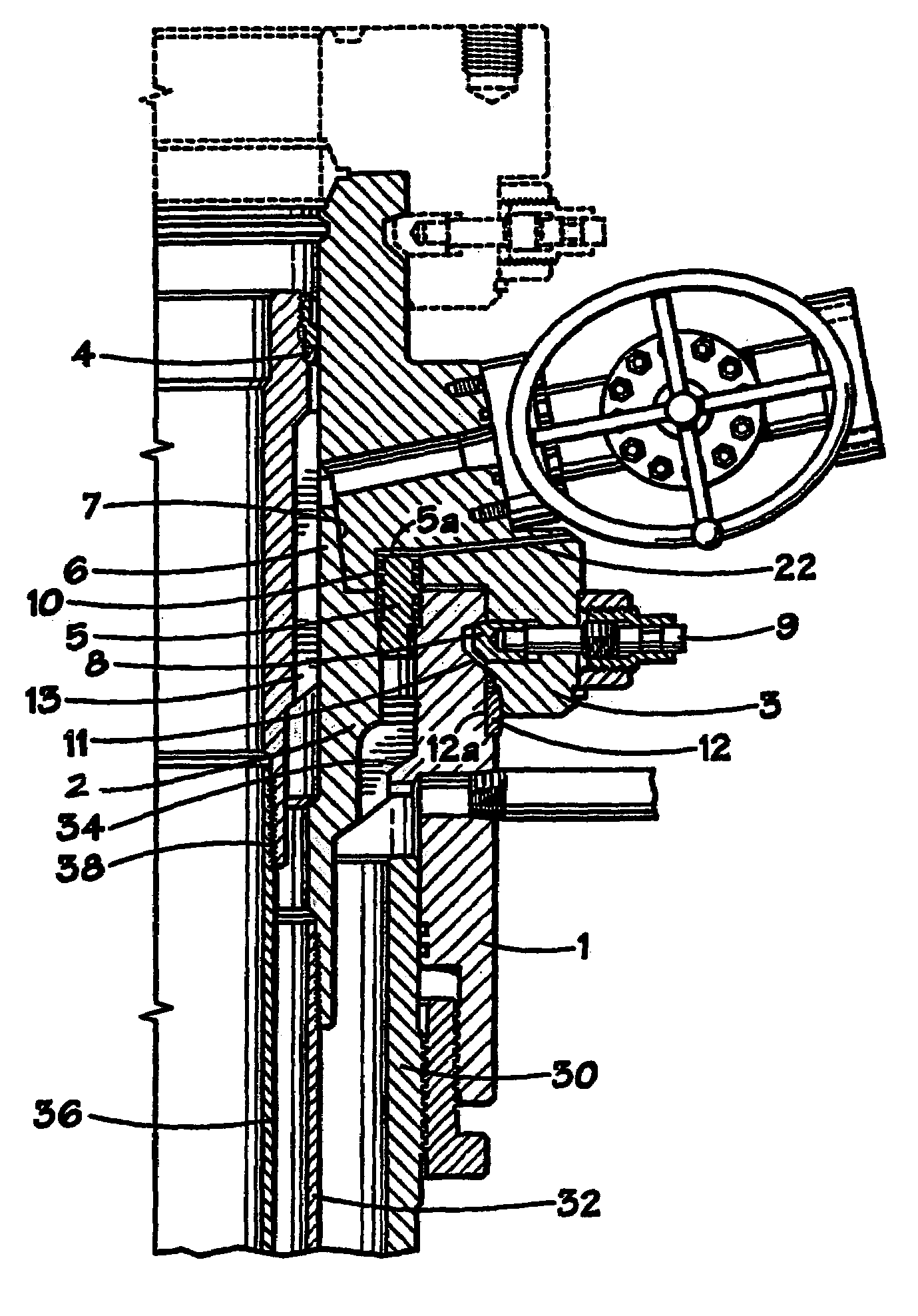
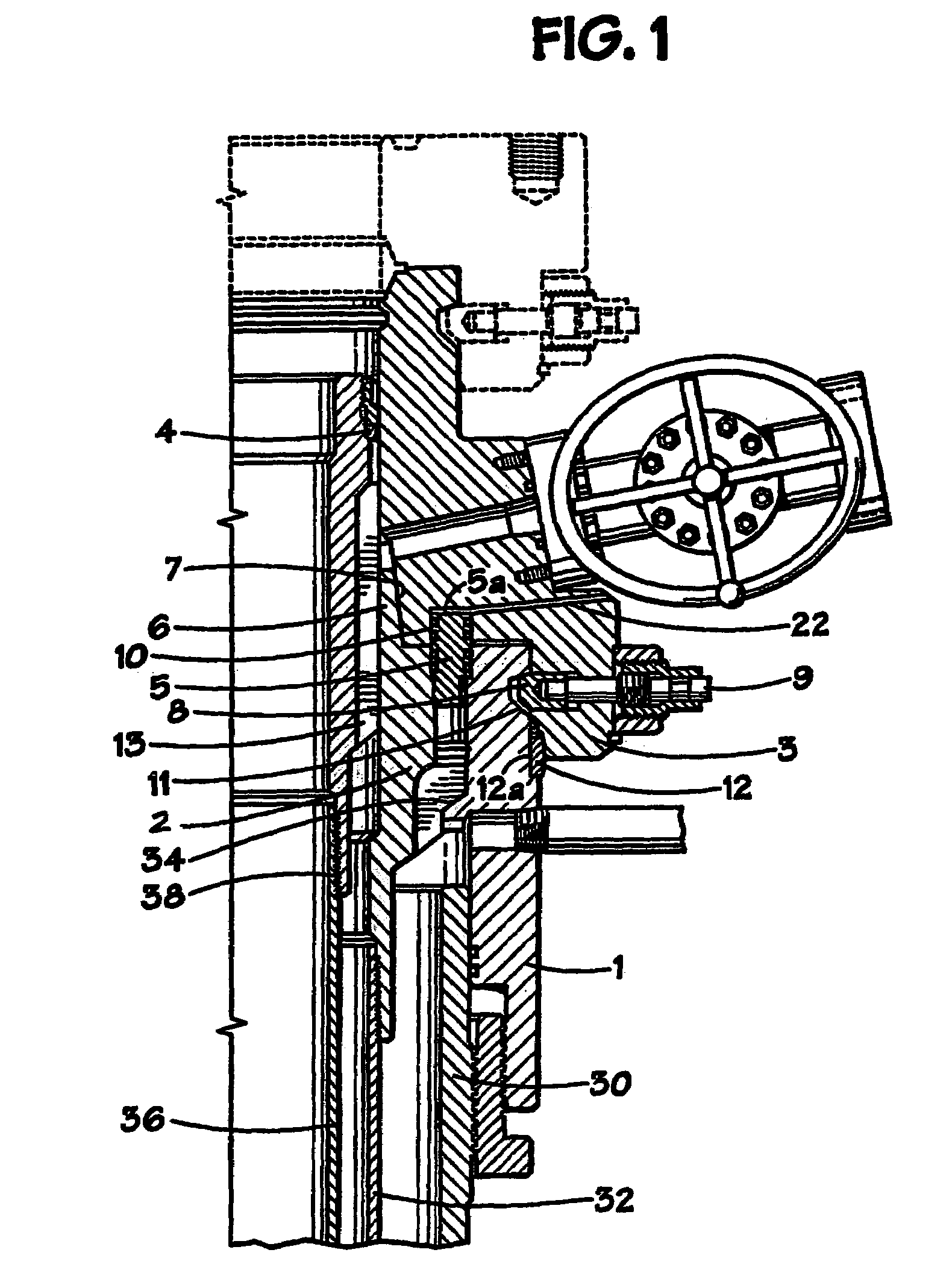
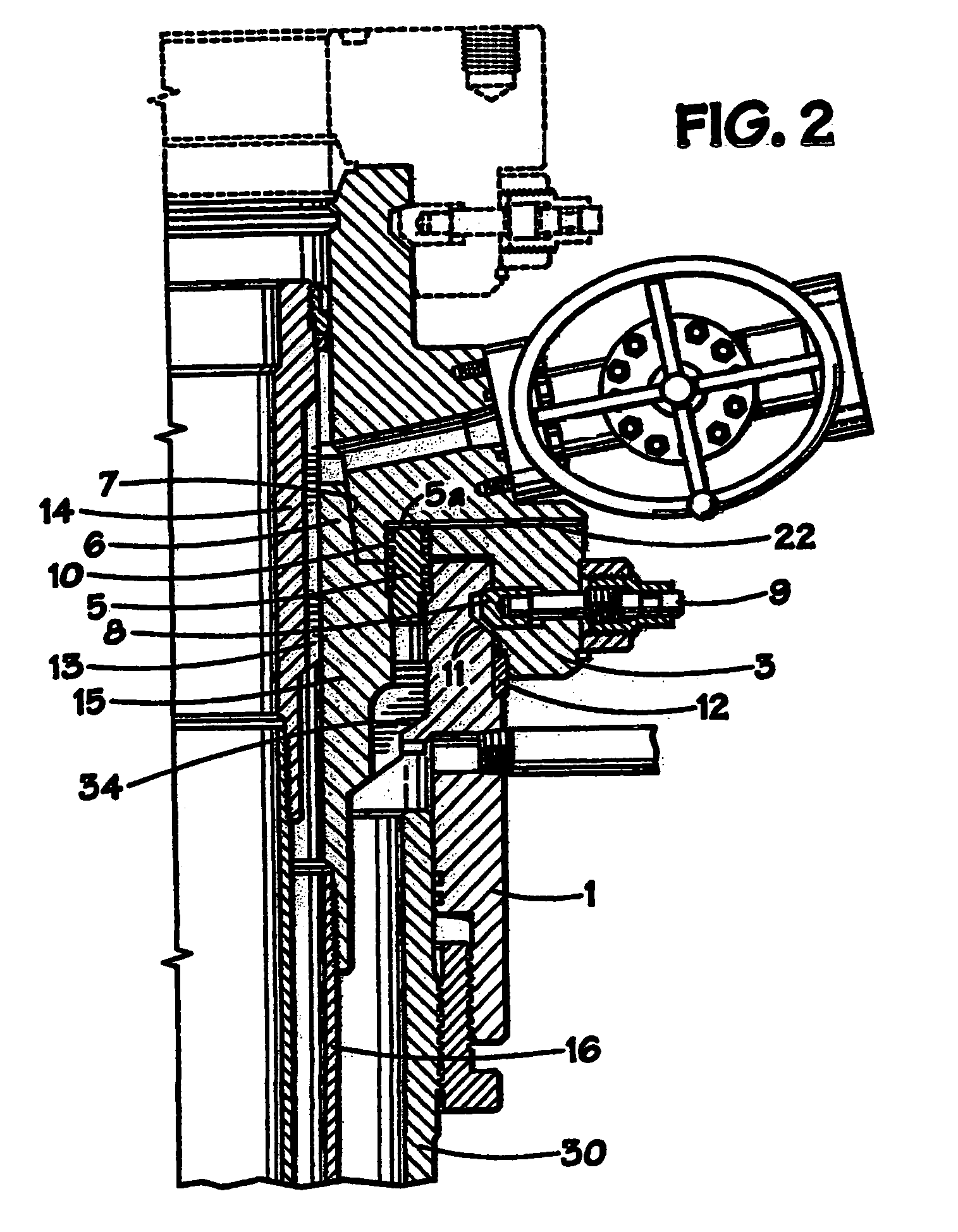
[0052]The adjustable wellhead shown in FIG. 1 has a surface casing starting head 1 mounted on a casing section 30. An intermediate casing 32 is located in the casing 30 and has a casing hanger 2 by means of which the casing is landed on a shoulder 34. The hanger 2 has an extended upper neck 6 which has a tapered external profile.

[0053]A wellhead spool 3 is shown above the casing hanger 2. The wellhead spool has a tapered internal profile 7 which mates with the tapered external profile of the neck 6 and, in the position shown in FIG. 1, the spool is supported above the hanger 2 on a spacer ring 12. An annular seal ring 5 fitted with O-rings 10 provides a seal between the spool 3, the starting head 1 and the casing hanger 2.

[0054]A chamber 5a is present above the seal ring 5. This chamber can be pressurized, through a passage 22, to raise the spool 3 above the starting head 1, and such raising action will have the effect of unloading the weight of the wellhead spool 3 from the spacer ...


PUM


Abstract

A clamp for clamping two concentric tubes, typically two concentric tubes in an oil or gas well. The clamp has two axially movable tapered components which can be pulled over one another in an axial direction to provide a contraction of internal diameter which grips the smaller diameter tube. In one embodiment, a spacer is fitted to allow the tapered components to be held apart until the tubes have been correctly positioned. The spacer is then removed, and the tapered components are drawn together to effect the clamping. A hydraulic ram can be provided to separate the tapered components should readjustment be required. In another embodiment, the larger diameter tube is made with a relatively thin wall, so that it can be distorted inwards to grip the smaller tube.

Description

CROSS-REFERENCE TO RELATED APPLICATIONS[0001]The present application is a divisional of U.S. Pat. No. 6,662,868 issued on Dec. 16, 2003, which is a continuation-in-part of now abandoned U.S. patent application Ser. No. 09 / 563,959 filed on May 3, 2000, which is a divisional of Ser. No. 09 / 179,056, filed Oct. 26, 1998, now U.S. Pat. No. 6,092,596 issued on Jul. 25, 2000.BACKGROUND OF THE INVENTION[0002]1. Field of the Invention[0003]This invention relates to the clamping of concentric well casings, where an inner well casing is to be clamped in position relative to an outer well casing, to achieve a desired relative axial position between the casings, for operational reasons axial fixing between coaxial well casings over a range of positions may be required at various times during drilling and / or production from wells, and the present invention makes it possible to clamp one or more casings within another at any desired position and subsequently to unclamp the casings for disassembly,...

Claims


Application Information

Patent Timeline
Patent Type & Authority Patents(United States)
IPC IPC(8): E21B17/18E21B19/16F16L19/06E21B19/00E21B33/038E21B33/04E21B33/047F16L39/00
CPCE21B19/004E21B33/038F16L39/005E21B33/0422E21B33/047E21B33/04
Inventor VANBILDERBEEK, BERNARD H.
Owner PLEXUS HOLDINGS PLC
Learn More