

Liquid discharge method and apparatus and display device panel manufacturing method and apparatus
a technology of display device and liquid crystal display device, which is applied in the direction of liquid handling, coupling device connection, instruments, etc., can solve the problems of high cost, high cost, and high demand for cost reduction, and achieve the effect of simple arrangemen
- Summary
- Abstract
- Description
- Claims
- Application Information
AI Technical Summary
Benefits of technology
Problems solved by technology
Method used
Image

Examples
first embodiment
(First Embodiment)
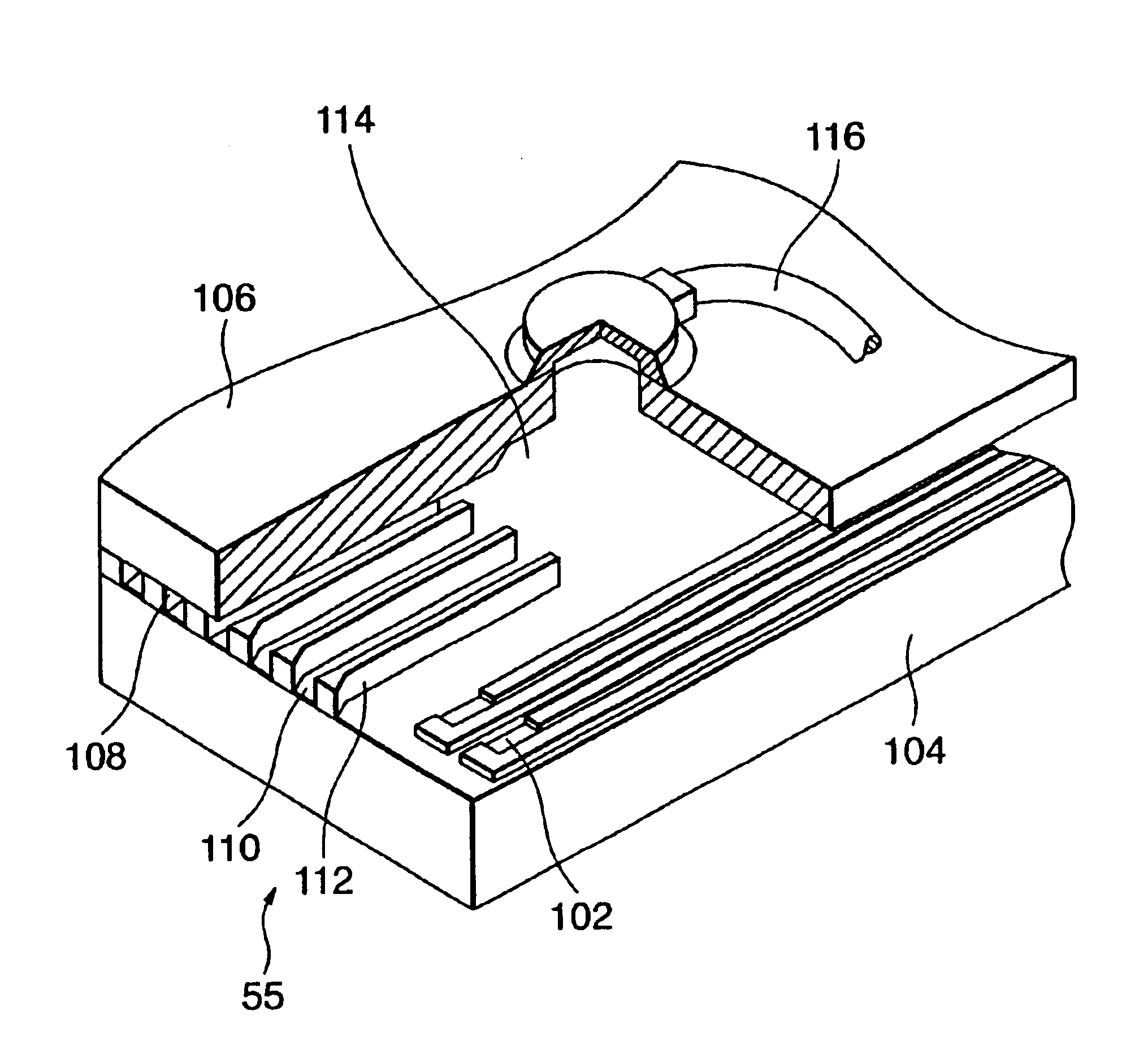
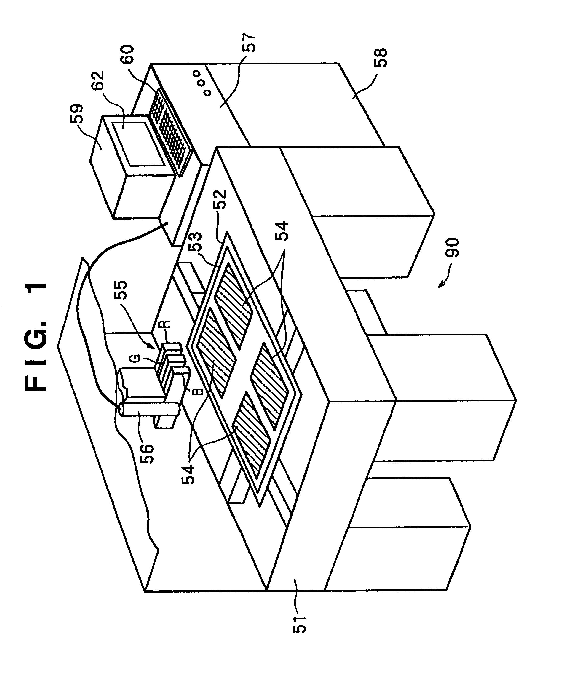
[0107]FIG. 1 is a schematic view showing the arrangement of a color filter manufacturing apparatus according to an embodiment.
[0108]Referring to FIG. 1, reference numeral 51 denotes an apparatus base; 52, an X-Y-θ stage disposed on the apparatus base 51; 53, a color filter substrate set on the X-Y-θ stage 52; 54, color filters formed on the color filter substrate 53; 55, red, green, and blue ink-jet heads for coloring the color filters 54; 58, a controller for controlling the overall operation of a color filter manufacturing apparatus 90; 59, a teaching pendant (personal computer) serving as the display unit of the controller; and 60, a keyboard serving as the operation unit of the teaching pendant 59.
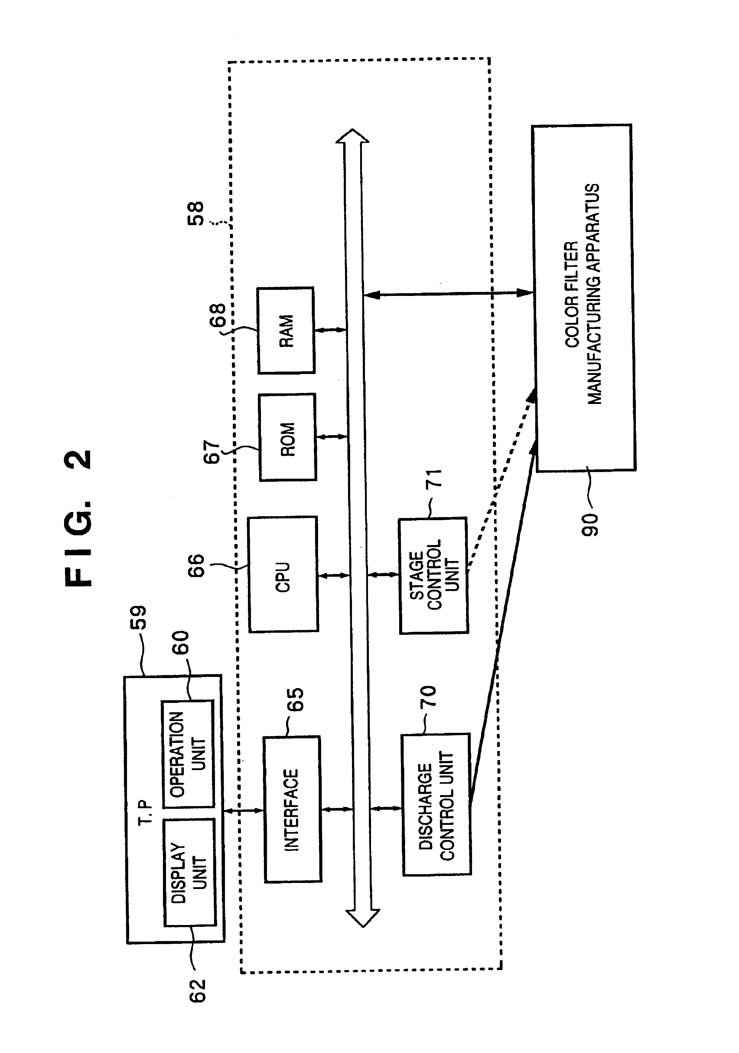
[0109]FIG. 2 is a block diagram showing the arrangement of the controller of the color filter manufacturing apparatus 90. Reference numeral 59 denotes a teaching pendant serving as the input / output device of the controller 58; 62, a display unit for displaying how a m...
modification to first embodiment
(Modification to First Embodiment)
[0169]In this modification, a discharge amount correction method used when a plurality of color filters with different sizes are manufactured from one glass substrate will be described.
[0170]FIG. 26 is a view showing a case wherein a plurality of color filters (a color filter having pixels A and a color filter having pixels B) having pixels with different sizes are manufactured from one glass substrate.
[0171]When ink is to be discharged to such pixels with different sizes, the amount of ink discharged from a nozzle must be changed in accordance with the size of a pixel. Referring to FIG. 26, since a nozzle of No. 9 is used to discharge ink to both the pixel A and the pixel B, the discharge amount must be changed when ink is discharged to the respective pixels. In this case, only the nozzle of No. 9 is used for printing for both kinds of pixels. In practice, however, nozzles other than the nozzle of No. 9 are used for printing to both kinds of pixels...
second embodiment
(Second Embodiment)
[0175]As described above, the amount of ink discharged from each nozzle is influenced by whether or not ink is discharged from adjacent nozzles and number of nozzles in use. The second embodiment is characterized in that driving conditions such as the driving voltage value applied to each nozzle and its pulse width are controlled in consideration of the influences of these factors. Other arrangements (e.g., the discharge amount control circuit shown in FIG. 18) are common to the first embodiment, and hence a description thereof will be omitted. In the second embodiment as well, a discharge amount changing device is provided in correspondence with each nozzle so as to independently change the ink discharge amount of each nozzle.
[0176]FIG. 29 is a flow chart showing color filter printing operation which is a characteristic feature of this embodiment. Referring to FIG. 29, “change printing stage” indicates that the size or resolution of a filter 54 to be formed, the ...
PUM
 Abstract
Description
Claims
Application Information