Piezoelectric resonator and assembly comprising the same enclosed in a case

a technology of piezoelectric resonators and assemblies, which is applied in piezoelectric/electrostrictive devices, impedence networks, electrical apparatus, etc., can solve the problems of affecting the manufacture of piezoelectric/electrostrictive devices, the ratio between their length and width is not very good for such cases, and the connection of conventional tuning fork resonators and cases are liable to tip towards the bottom of the cas

Active Publication Date: 2006-09-26
ETA SA MFG HORLOGERE SUISSE
View PDF8 Cites 18 Cited by
  • Summary
  • Abstract
  • Description
  • Claims
  • Application Information

AI Technical Summary

Benefits of technology

[0010]The main goal of the present invention is to overcome the aforecited drawbacks by providing a three arm resonator along with its packaging which in combination enables to mount the resonator securely inside its packaging while preventing short-circuit between the electrodes on the central arm of the resonator due to conductive adhesive leakage.
[0015]wherein guiding means are provided at least with either the first connection pad or element being located on the linking part side in order to flow the conductive adhesive away from the second electrode being not electrically connected to the first connection pad or element with the guiding means. Thus this guiding means allow preventing short-circuit between electrodes on the central arm of the resonator.
[0018]According to another aspect of the invention, the guiding means include at least one first bump arranged along either the first connection element or pad between the latter and the second electrode which bump prevents the excess of conductive adhesive from flowing toward the second electrode when gluing the resonator on the support.
[0019]According to another aspect of the invention, the guiding means, in addition to a first bump arranged along either the first connection element or pad, further include two other bumps arranged orthogonally to the first bump and along lateral sides of the first connection element or pad. This U-shaped barrier efficiently prevents the excess of conductive adhesive from flowing toward the second electrode when gluing the resonator on the support.
[0020]According to another aspect of the invention, the guiding means are provided with both the first connection pads or elements and the second connection pads or elements. This symmetric arrangement prevents from having a different spreading of the conductive adhesive in the respective gluing zones of the first and second connection elements when gluing the resonator on the support.

Problems solved by technology

One of these problems is that the dimensional and functional features of the conventional tuning fork resonators are optimised for mounting them in metallic cases and not in ceramic cases.
For example, the ratio between their length and their width is ill suited to the manufacture of such cases, in particular when the cases are of the SMD (Surface Mounting Device) type, i.e. meant to be automatically mounted on hole-free printed circuit boards.
Because of this, a conventional tuning fork resonator and its connection to the case do not have very good resistance to shocks.
Further conventional tuning fork resonators are liable to tip towards the bottom of the case when it is fixed onto a step of the case.
Furthermore, since the thermal expansion coefficients of ceramic material and quartz are different enough to create mechanical stresses in the resonator which can not only be felt in the arms of the tuning fork and disturb the working of the resonator when the temperature changes but can also break the solder or detach connection pads of the resonator from those of the case and alter or even cut the electric connection between the resonator electrodes and the external contact pads of the case.
For the same reason, if there is an incipient fracture on the side of base of the tuning fork where connection pads are situated, a significant temperature variation can even break the tuning fork.

Method used


Image

  • Piezoelectric resonator and assembly comprising the same enclosed in a case
  • Piezoelectric resonator and assembly comprising the same enclosed in a case
  • Piezoelectric resonator and assembly comprising the same enclosed in a case

Examples


first embodiment

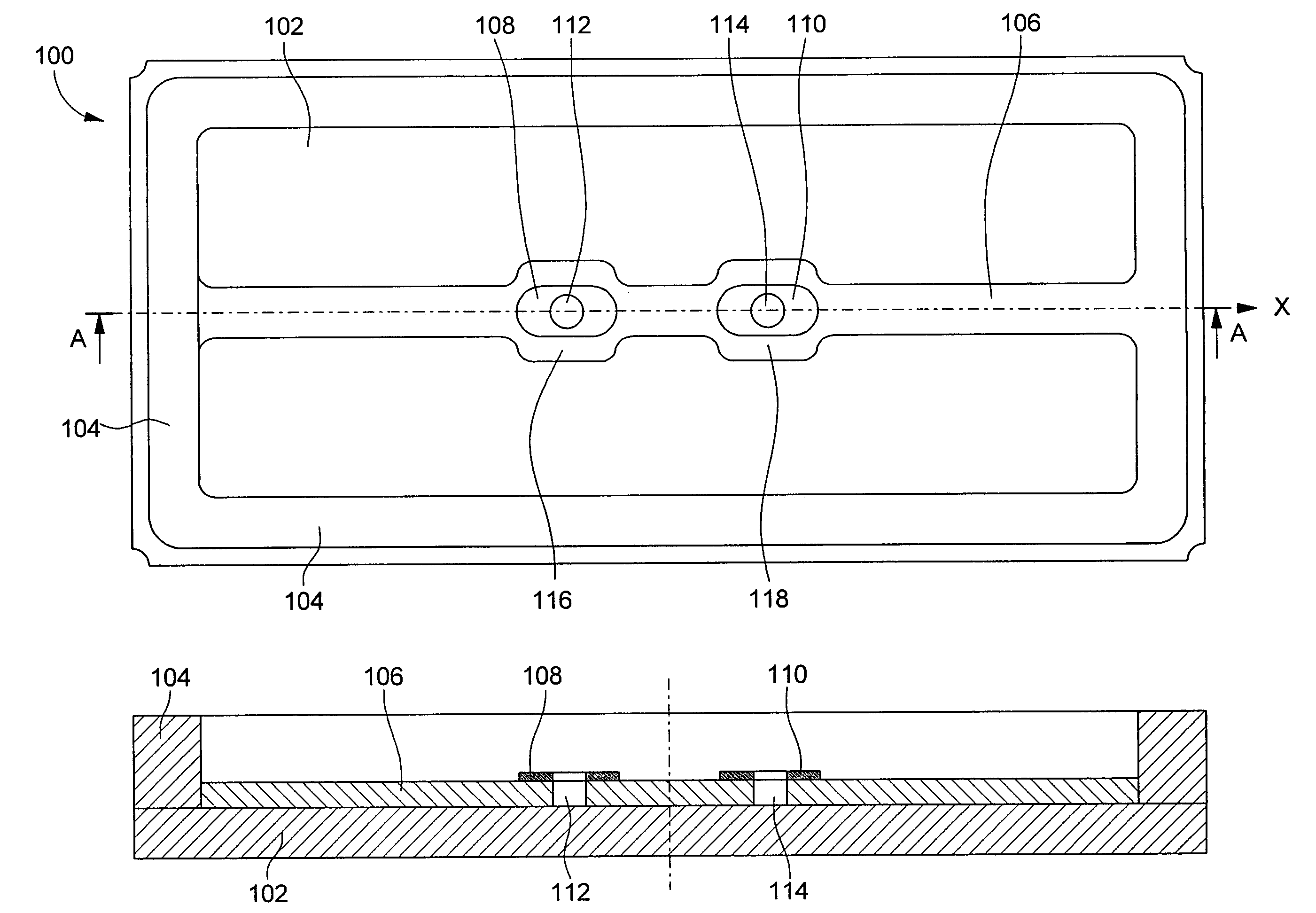
[0037]Further, in order to prevent leakage of the conductive adhesive when gluing the resonator into the package, guiding means are provided at least with one conductive element and preferably both elements 108 and 110. According to the invention, these guiding means are holes 112, 114 cut through conductive layers 108 and 110 and at least partly through rib 106. Preferably, rib 106 is further provided with wider portion 116, 118 at least on both sides of conductive elements 108, 110 in order to assure a better support for the resonator.

second embodiment

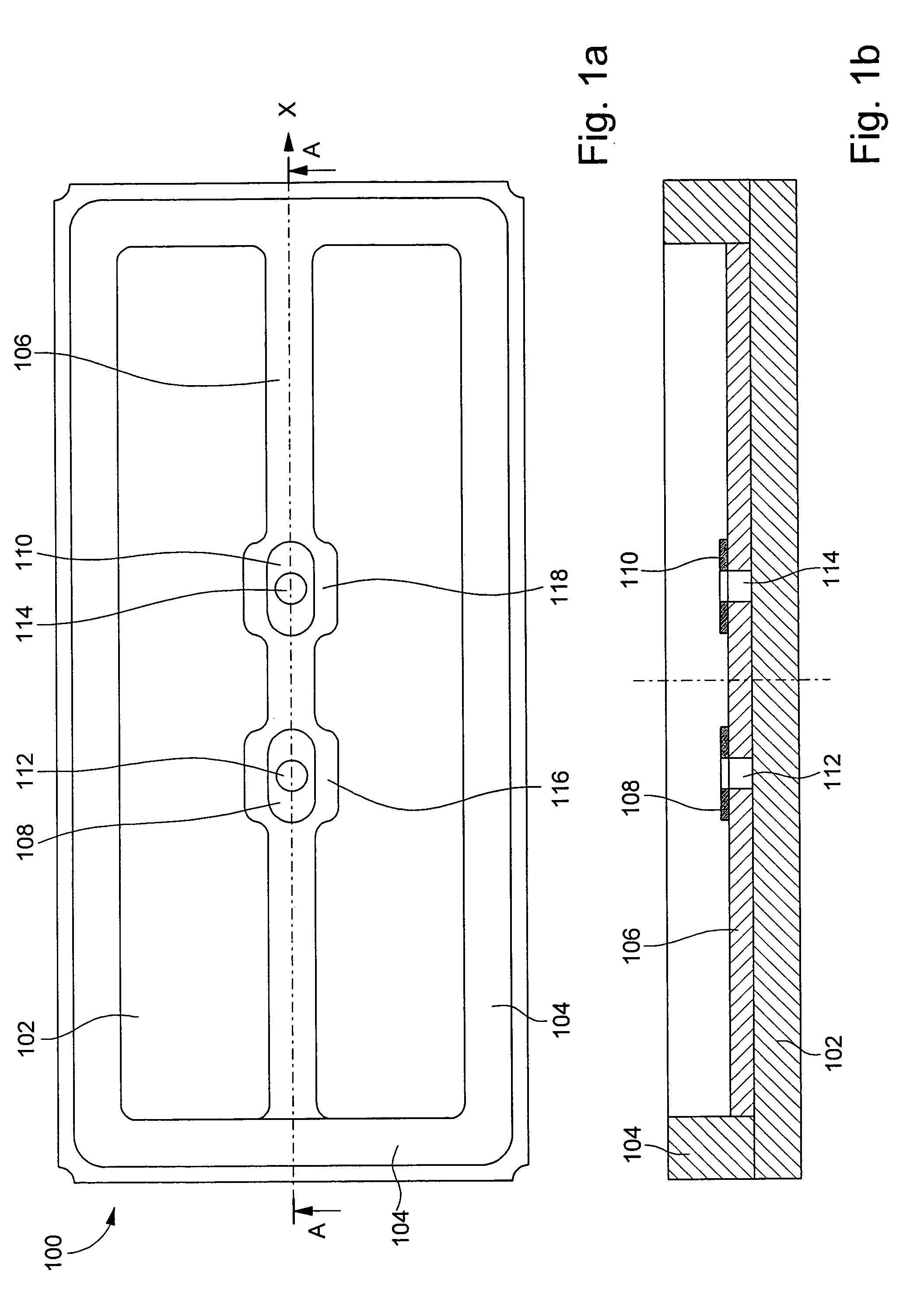
[0038] shown in relation of FIGS. 2a and 2b, the guiding means are implemented in the form of recesses 120 and 122 respectively cut in conductive elements 108 and 110 and in support 106 on the opposite side from the one where the electrode arranged on the central arm of the resonator is located, as it will be described hereinafter in relation with FIG. 10c.

third embodiment

[0039] shown in relation with FIGS. 3a and 3b, the guiding means include bumps 124 and, preferably, 126 respectively arranged along connection elements 108 and 110 in order to be located between the latter and the electrode located on the back face of the central as it will be shown in FIG. 10b. Alternatively, these bumps may be provided on the back face of the resonator instead on support 106. These bumps 124 and 126 advantageously extend on the whole length of the conductive elements (or pads for the alternative on the resonator). Furthermore, additional bumps 128a and 128b, respectively 130a and 130b, substantially perpendicular to bump 124, respectively 126, have been provided on conductive element 108, respectively 110 (or alternatively on connecting pads of the resonator). Thus the three bumps 124, 128a and 128b, respectively 126, 130a and 130b, form a U-shaped barrier that efficiently prevents the excess of conductive adhesive from flowing towards the electrode located on the...


PUM


Abstract

The invention concerns an assembly comprising a piezoelectric resonator and a case, said case including a main part with a bottom and sides, in which said resonator is mounted and a cover fixed to said main part, said resonator including a tuning fork shaped part with two parallel vibrating arms connected to each other by a linking part, and a central arm protruding from said linking part and located between both vibrating arms carrying at least two electrodes to make them vibrate, these two electrodes being connected respectively to at least first and second connection pads located on a back face of said central arm oriented toward the bottom of the case, said case further comprising at least one support secured to its bottom on which said central arm of the resonator is fixed by means of at least first and second connection elements located on said support and electrically connected respectively to said first and second connection pads by a conductive adhesive, wherein guiding means are provided at least with either said first connection pad or element being located on the linking part side in order to flow excess of said conductive adhesive away from the second electrode being not electrically connected to said first connection pad or element with said guiding means.

Description

FIELD OF INVENTION[0001]The present invention concerns piezoelectric resonators and more particularly resonators of small dimensions which are most often used for making frequency generators in particular for portable electronic equipment, in numerous fields such as horology, information technology, telecommunications and the medical field.BACKGROUND OF THE INVENTION[0002]Such a resonator of small dimensions has been disclosed in the prior art document U.S. Pat. No. 6,700,313 filed in the name of the name Assignee, which is enclosed herewith by way of reference. Resonator 10 represented on FIG. 12, which is intended to be mounted in a case, includes a tuning fork shaped part with two parallel arms 12, 14 connected to each other by a linking part 16 and carrying electrodes 20, 22 to make them vibrate, these electrodes being connected to connecting pads 28, 30 intended to be electrically connected to the exterior of the case. Resonator 10 also includes a central arm 18 attached to lin...

Claims


Application Information

Patent Timeline
Patent Type & Authority Patents(United States)
IPC IPC(8): H01L41/08
CPCH03H9/21H03H9/1021
Inventor DALLA PIAZZA, SILVIOSTUDER, BRUNOLUETHI, THOMAS
Owner ETA SA MFG HORLOGERE SUISSE
Why Eureka
Try Eureka