Systems, apparatus and method for reducing dust on components in a computer system

a computer system and component technology, applied in the field of computer systems, can solve the problems of reducing the dust on the components of the computer system, affecting the performance of the system, and the failure of the component and potentially the entire pc, so as to reduce the dust

Inactive Publication Date: 2006-09-26
LENOVO (SINGAPORE) PTE LTD
View PDF10 Cites 38 Cited by
  • Summary
  • Abstract
  • Description
  • Claims
  • Application Information

AI Technical Summary

Problems solved by technology

Many components of PCs generate heat during operation, making it necessary to cool those components so that proper functioning continues, particularly because of the confined space of the enclosure which makes it more difficult to reject waste heat.
Dust may then gather on critical components, eventually resulting in failure of that component and potentially the entire PC.
The problem of accumulated dust is exacerbated for thermally-sensitive components, as dust accumulations contribute to overheating and eventual failure.
Accumulation of dust may result in a safety hazard as well.
Dust on a heat generating component typically heats up with that component, which may result in a fire.
Manually blowing out or removing the dust with a vacuum clean are time-consuming for the user, making them undesirable.
Moreover, these methods rely on activity that may not be performed, particularly if users are asked to do the work themselves, and therefore do not prevent the accumulation of dust in many cases.
These methods also require for the computer to be turned off in order to open the system up for dust blowing or removal, resulting in downtime for the system.
Because of their cost, complication, and ineffectiveness, these methods do not provide a satisfactory solution for many users.
Filtration systems, however, are somewhat inefficient, particularly for small particles, resulting in significant amounts of dust still entering.
Another problem with filtration systems is that they can drastically reduce the amount of air entering the system, making cooling more difficult.
Neither solution is desirable as they increase costs and run the risk of creating more noise.

Method used


Image

  • Systems, apparatus and method for reducing dust on components in a computer system
  • Systems, apparatus and method for reducing dust on components in a computer system
  • Systems, apparatus and method for reducing dust on components in a computer system

Examples


Embodiment Construction

[0017]The following is a detailed description of example embodiments of the invention depicted in the accompanying drawings. The example embodiments are in such detail as to clearly communicate the invention. However, the amount of detail offered is not intended to limit the anticipated variations of embodiments; but, on the contrary, the intention is to cover all modifications, equivalents, and alternatives falling within the spirit and scope of the present invention as defined by the appended claims. The detailed descriptions below are designed to make such embodiments obvious to a person of ordinary skill in the art.

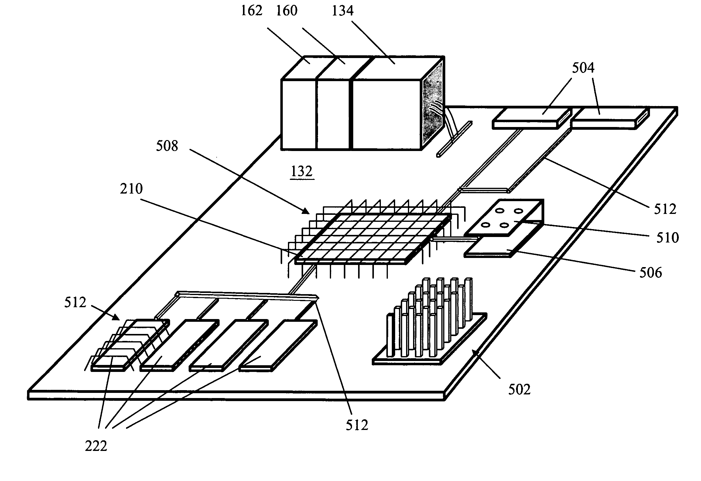
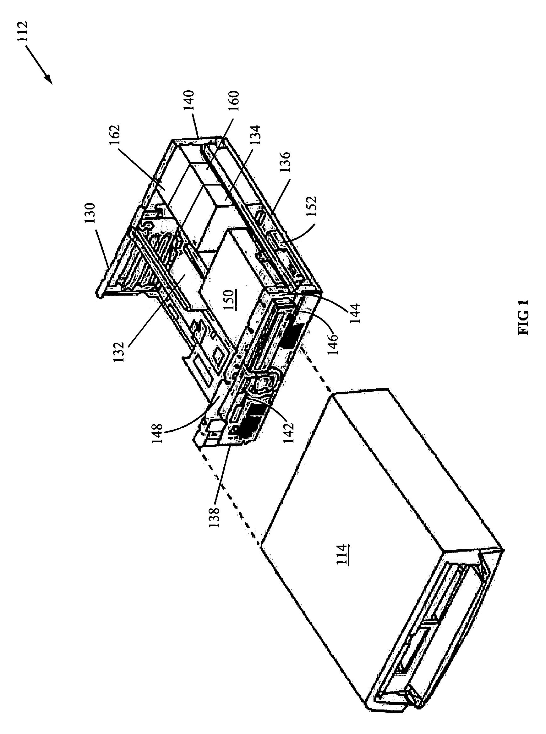
[0018]An apparatus and method for reducing dust on components in a computer system is disclosed. Embodiments include a system that generally includes an enclosure, a component mounted with the enclosure, and a fan adapted to induce an airflow towards the component to provide cooling. The system also generally includes a dust ionizer adapted to provide an electrical ch...


PUM


Abstract

An apparatus and method for reducing dust on components in a computer system is disclosed. Embodiments include a system that generally includes an enclosure, a component mounted with the enclosure, and a fan adapted to induce an airflow towards the component to provide cooling. The system also generally includes a dust ionizer adapted to provide an electrical charge to dust particles within the airflow and a dust reflector having an electrical charge adapted to deflect the charge dust particles away from the component. In some embodiments, the component may be a processor, heat sink, video chip, memory module, voltage regulator module, etc.

Description

FIELD OF INVENTION[0001]The present invention is in the field of computer systems. More particularly, the present invention relates to a method and apparatus for reducing dust on components in a computer system.BACKGROUND[0002]Personal computer (PC) systems are well known in the art. They have attained widespread use in many segments of today's modern society as a result of their widespread use for telecommuting, news, stock market information and trading, banking, shopping, shipping, communication in the form of hypertext transfer protocol (http) and email, as well as other services. PCs are typically provided with enclosures which protect the operating components of the computer, provide an aesthetically pleasing appearance, and shield against undesirable emission of electromagnetic energy.[0003]Many components of PCs generate heat during operation, making it necessary to cool those components so that proper functioning continues, particularly because of the confined space of the ...

Claims


Application Information

Patent Timeline
Patent Type & Authority Patents(United States)
IPC IPC(8): H05K7/20
CPCG06F1/20
Inventor RUTLEDGE, JAMES STEPHENCHAPMAN, CORY ALLENSEETHALER, KENNETH SCOTTDUNCAN, WILLIAM STEPHEN
Owner LENOVO (SINGAPORE) PTE LTD
Why Eureka
Try Eureka