
Wing for an aircraft or spacecraft

a technology for spacecraft and wings, applied in the field of wings for spacecraft, can solve problems such as shock waves, and achieve the effects of improving the strengthening the effect of meandered fins, and good mechanical properties of grid fins

Active Publication Date: 2006-10-03
DEUTSCHES ZENTRUM FUER LUFT & RAUMFAHRT EV
View PDF15 Cites 21 Cited by
  • Summary
  • Abstract
  • Description
  • Claims
  • Application Information

AI Technical Summary

Benefits of technology

[0013]The airflow related to supersonic speeds of flying objects causes shock waves. As one result of the meandered design of the leading edge contours, the caused crossing shock waves interaction can leads to further reducing of wing's wave drag.
[0051]According to another embodiment of the invention, the fins of the grid fins are supported by a frame. The frame can be used in order to increase the stiffness of the grid fins as well as in order to connect the grid fins to the flying object. In case that it is desired to change the inclination of the grid fins with respect to the flying object and thus to change the flow direction of the airflow with respect to the grid fins, the grid fins may be linked pivotably with the flying object, for instance by means of a hinge in combination with a suitable actuator. According to another embodiment of the invention, wherein the frame is designed and configured in a multifunctional way the contour of the frame is also meandered. In such case the frame is additionally to the aforementioned functions also used to influence the aerodynamic properties and to strengthen the effect of the meandered fins.

Problems solved by technology

The airflow related to supersonic speeds of flying objects causes shock waves.

Method used


Image

  • Wing for an aircraft or spacecraft
  • Wing for an aircraft or spacecraft
  • Wing for an aircraft or spacecraft

Examples


Embodiment Construction

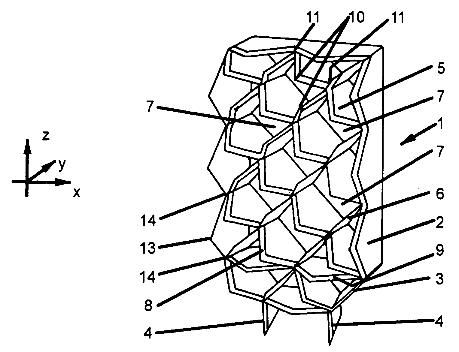
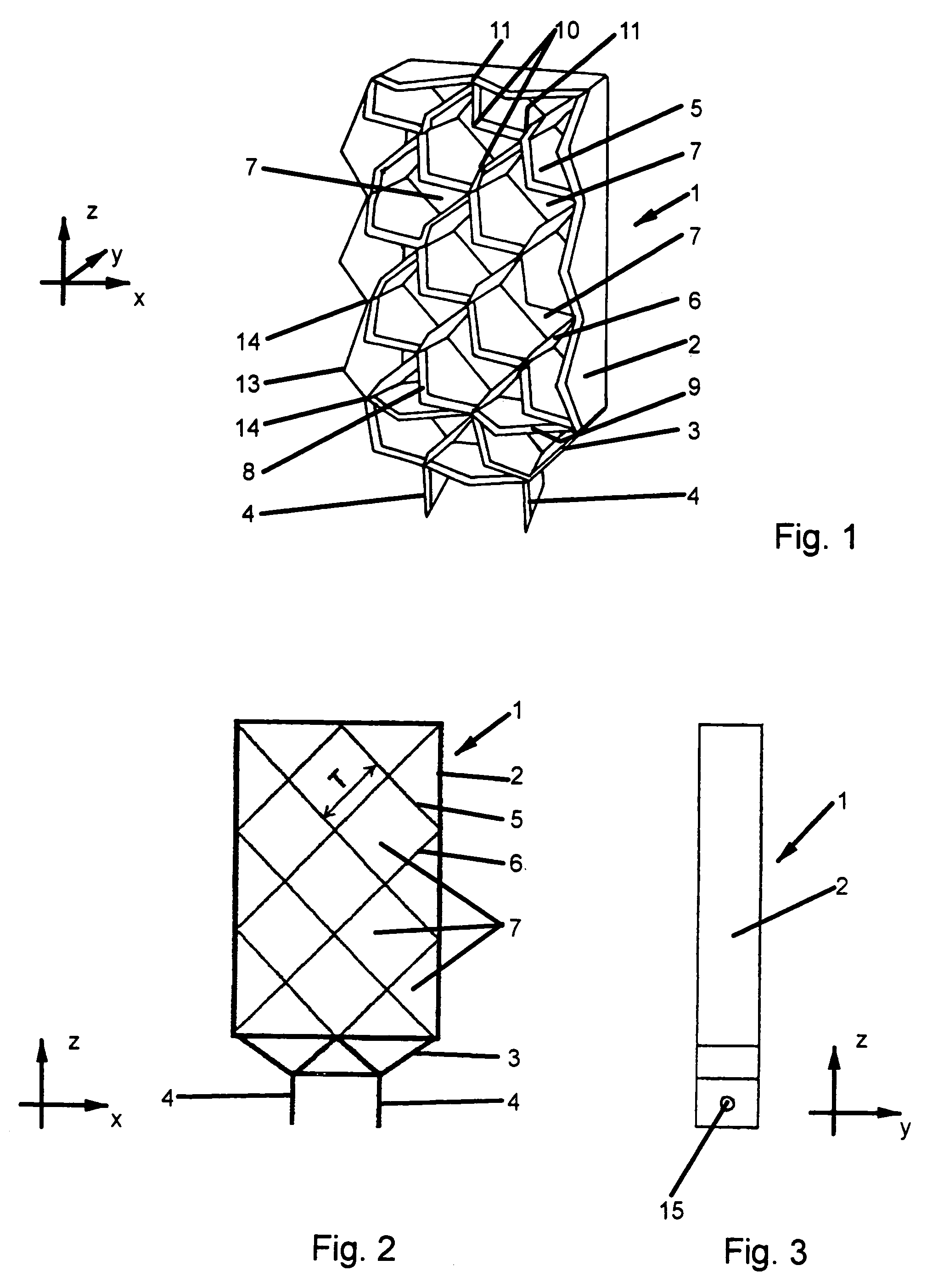
[0070]In the following the invention is explained on the basis of a special embodiment which is a grid fin 1. A transfer of the basic principles explained on the basis of the grid fin 1 to any other suitable wing, surface, lifting element, guiding element; steering element or tail unit is possible and included into the subject-matter of the appended claims, for instance surfaces being a part of a nacelle, wings or guiding elements for a flying object, inflow regions or inflow ducts. The combination of different features shown in different figures or mentioned in connection with different uses is also possible.

[0071]A grid fin 1 is linked in a fixed manner or pivotably linked with a flying object, in particular with an aircraft, a projectile, a rocket, a missile or a space vehicle. The grid fin 1 comprises a frame 2 of rectangular outer shape, the bottom of the frame comprising a tapering 3 with two holding elements 4 extending from the tapering 3. Sets of parallel fins 5 and paralle...


PUM


Abstract

The invention relates to a wing, a wing, a tail unit or grid fins for a flying object moving with supersonic speeds. The wing comprises leading edges and tailing edges.According to the invention, the contour of at least one of the leading contour and the tailing contour has a meandered shape.By means of the inventive meandered contours the wave drag of the flying object may be decreased. The inventive design of the leading or tailing edges of a wing can be used for aircrafts, spacecrafts, missiles, projectiles and the like.

Description

CROSS REFERENCE TO RELATED APPLICATIONS[0001]This application claims priority to co-pending German Patent Application No. 10 2004 026 625.5 entitled “Gitterflügel”, filed Jun. 1, 2004. Additionally the application claims priority to co-pending German Patent Application No. 10 2005 005 234.7 entitled “Trag- oder Leitelement”, filed Feb. 4, 2005.FIELD OF THE INVENTION[0002]The present invention generally relates to lifting, tail or control surfaces, named further uniform wings (in the following “wings”) for flying objects as aircrafts, spacecrafts, projectiles or missiles for use with transonic, supersonic or hypersonic speeds.BACKGROUND OF THE INVENTION[0003]The drag of air leads to energy losses that increase exponentially with increasing speed of a flying object. Furthermore, the drag leads to mechanical loads and stresses acting upon the constructive elements of the flying object. These loads and stresses have to be considered when dimensioning the flying object. Accordingly, the ...

Claims


Application Information

Patent Timeline
IPC IPC(8): B64C21/10B64C3/10B64C5/00F42B10/04F42B10/14
CPCB64C3/10B64C5/00F42B10/04B64D2033/026Y02T50/12F42B10/143Y02T50/10
Inventor SCHULEIN, ERICH
Owner DEUTSCHES ZENTRUM FUER LUFT & RAUMFAHRT EV
Learn More