Optical assembly and projector

a technology of optical assembly and projector, applied in the direction of picture reproducers using projection devices, polarising elements, instruments, etc., can solve the problems of wv film, polarizing plate, etc., which cannot be sufficiently guaranteed, and achieve the effect of reducing or preventing the deterioration of the optical compensation element and enhancing the contrast of image display

Inactive Publication Date: 2006-10-03
SEIKO EPSON CORP
View PDF20 Cites 12 Cited by
  • Summary
  • Abstract
  • Description
  • Claims
  • Application Information

AI Technical Summary

Benefits of technology

[0010]In the above optical assembly, the optical compensation element whose rotational position can be adjusted by the holding member is disposed between the optical modulation element and the second polarizing plate. Therefore, for example, an unintended birefringent action, i.e., the phase difference generated on the incident and emission sides of the optical modulation element is eliminated by adjusting the rotational position of the optical compensation element, thus enabling an enhancement in the contrast of image display. Furthermore, the first polarizing plate is disposed directly opposite the incident side of the optical modulation element. Therefore, the optical compensation element can be reduced or prevented from deteriorating with age, as compared with when the optical compensation element is disposed between the optical modulation element and the first polarizing plate. That is, when disposed on the incident side of the optical modulation element, the optical compensation element is exposed to comparatively strong illumination light, so that its optical characteristics are easy to change. And, particularly, when illumination light including ultraviolet light is incident on the optical compensation element, it becomes necessary to replace the optical compensation element at periodic intervals. In the optical assembly of an exemplary aspect of the invention, the optical compensation element is disposed only on the emission side of the optical modulation element. Therefore, the optical modulation element serves as a filter to enable reduction or prevention of the deterioration in characteristics of the optical compensation element, so that the contrast of image display can be maintained over a long period of time.
[0020]In the above projector, illumination light beams of individual colors are incident on optical modulation devices for the respective colors, then modulated into image light beams of the respective colors by the optical modulation devices for the respective colors, and thereafter combined by the light combining member. And, the image light combined by way of the projection optical system is projected onto a screen. On this occasion, such an optical assembly as above according to an exemplary aspect of the invention is used, so that it is possible to easily enhance the contrast of image display while reducing or preventing deterioration of the optical compensation element.

Problems solved by technology

However, when the WV film is disposed on the incident side of the liquid crystal element as in the above projection type liquid crystal display apparatus, the WV film is exposed to strong illumination light, so that its characteristics gradually deteriorate due to a change with age.
However, because of the cost of such a cross dichroic prism and a limitation in the back focus of a projection lens, a space for assembling the WV film, the polarizing plate, etc. cannot be sufficiently ensured between the liquid crystal display element and the cross dichroic prism.
Consequently, the WV film, the polarizing plate, etc. come into a close-packed state and thus become insufficiently cooled, or as regards the WV film on the emission side, it is obliged to omit the system of adjusting the rotational position thereof.

Method used


Image

  • Optical assembly and projector
  • Optical assembly and projector
  • Optical assembly and projector

Examples


Embodiment Construction

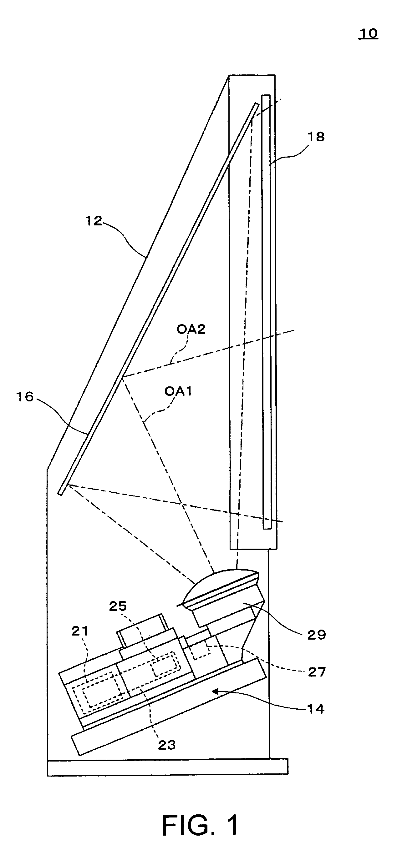
[0031]FIG. 1 is a schematic illustrating an entire structure of a projector according to an exemplary embodiment of the invention. This projector 10 is a rear projection type apparatus for displaying images by rear projection. The projector 10 includes a projector main body 14 at the bottom of a casing 12 serving as a housing, a reflecting mirror 16 at the rear upper portion within the casing 12, and a transmission screen member 18 at the front of the casing 12. Image light emitted from the projector main body 14 travels diagonally upwardly in the rearward direction with an optical axis OA1 as its center, is bent toward the front side by the reflecting mirror 16 with an optical axis OA2 as its center, and is incident on a screen portion provided on the transmission screen member 18. Additionally, the projector main body 14, the reflecting mirror 16, and the transmission screen member 18 are positioned and fixed within the casing 12.

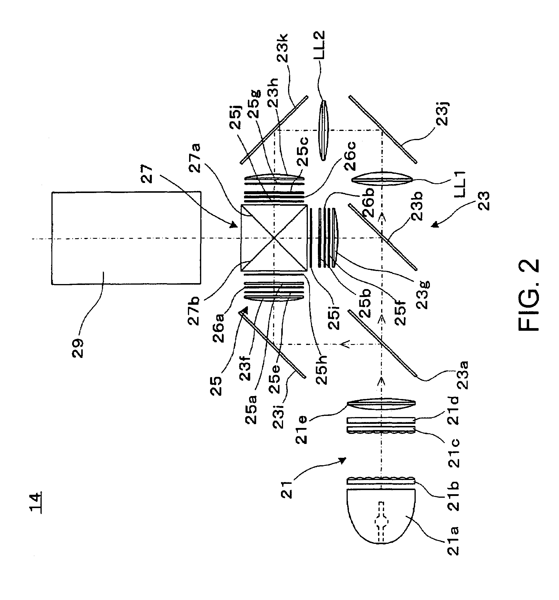
[0032]FIG. 2 is a schematic illustrating a structur...


PUM

PropertyMeasurementUnit
forceaaaaaaaaaa
coloraaaaaaaaaa
dielectricaaaaaaaaaa

Abstract

To provide an optical assembly capable of enhancing black level display while preventing deterioration of a WV film, and a projector assembled therewith, optical compensation elements are disposed before and after liquid crystal light valves, so that an unintended phase difference generated on the incident and emission sides of the liquid crystal light valves for individual colors is eliminated by adjusting the rotational positions of the optical compensation elements, thus enabling an enhancement in the contrast of a color image displayed on a transmission screen member. In case of B light including ultraviolet light in part, the optical compensation element is disposed at the subsequent stage of the liquid crystal light valve, so that as compared with when the optical compensation element is disposed at the preceding stage of the liquid crystal light valve, the optical compensation element can be reduced or prevented from deteriorating with age, thus enabling the contrast of image display to be maintained over a long period of time.

Description

BACKGROUND OF THE INVENTION[0001]1. Field of Invention[0002]Exemplary aspects of the present invention relate to an optical assembly including a liquid crystal element and another optical modulation device, and to a projector assembled with such an optical assembly.[0003]2. Description of Related Art[0004]A related art projection type liquid crystal display apparatus includes a liquid crystal display element for optical modulation, an incident side polarizing plate disposed on the incident side of the liquid crystal display element, an emission side polarizing plate disposed on the emission side thereof, and a pair of optical compensation elements one of which is disposed between the liquid crystal display element and the incident side polarizing plate, and the other of which is disposed between the liquid crystal display element and the emission side polarizing plate (see JP-A-2002-182213). In this related art projection type liquid crystal display apparatus, the optical compensati...

Claims


Application Information

Patent Timeline
Patent Type & Authority Patents(United States)
IPC IPC(8): G03B21/14G03B21/02G02B5/30G02F1/13G02F1/1333G02F1/1335G02F1/13363G03B21/00H04N9/31
CPCH04N9/3105H04N9/3144H04N9/315H04N9/3197G02F1/13
Inventor ARAI, JUNFUJIMORI, EIJIROKOBAYASHI, HIDEYUKIKUROSAWA, SHOGO
Owner SEIKO EPSON CORP
Why Eureka
Try Eureka