Variable camber and stagger airfoil and method

a technology of camber and airfoil, which is applied in the direction of machines/engines, stators, liquid fuel engines, etc., can solve the problems of aerodynamic inefficiency, aerodynamic loss, and simple operation of igv, and achieve optimal air flow and power turn down operation efficiency.

Active Publication Date: 2006-10-03
GENERAL ELECTRIC CO
View PDF5 Cites 77 Cited by
  • Summary
  • Abstract
  • Description
  • Claims
  • Application Information

AI Technical Summary

Benefits of technology

[0005]The invention improves power turn down operational efficiency by aerodynamic optimal air flow advantage through a variable stagger and camber inlet guide vane airfoil configuration.

Problems solved by technology

The IGV operation is simple, but aerodynamically inefficient.
This efficiency loss is attributable to the aerodynamic inefficiencies associated with a conventional IGV configuration.
Conventional variable geometry compressor airfoils are limited to either stagger-only or camber-only changes.
Thus, conventional variable geometry compressor airfoils do not have both variable camber and stagger control.

Method used


Image

  • Variable camber and stagger airfoil and method
  • Variable camber and stagger airfoil and method
  • Variable camber and stagger airfoil and method

Examples


Embodiment Construction

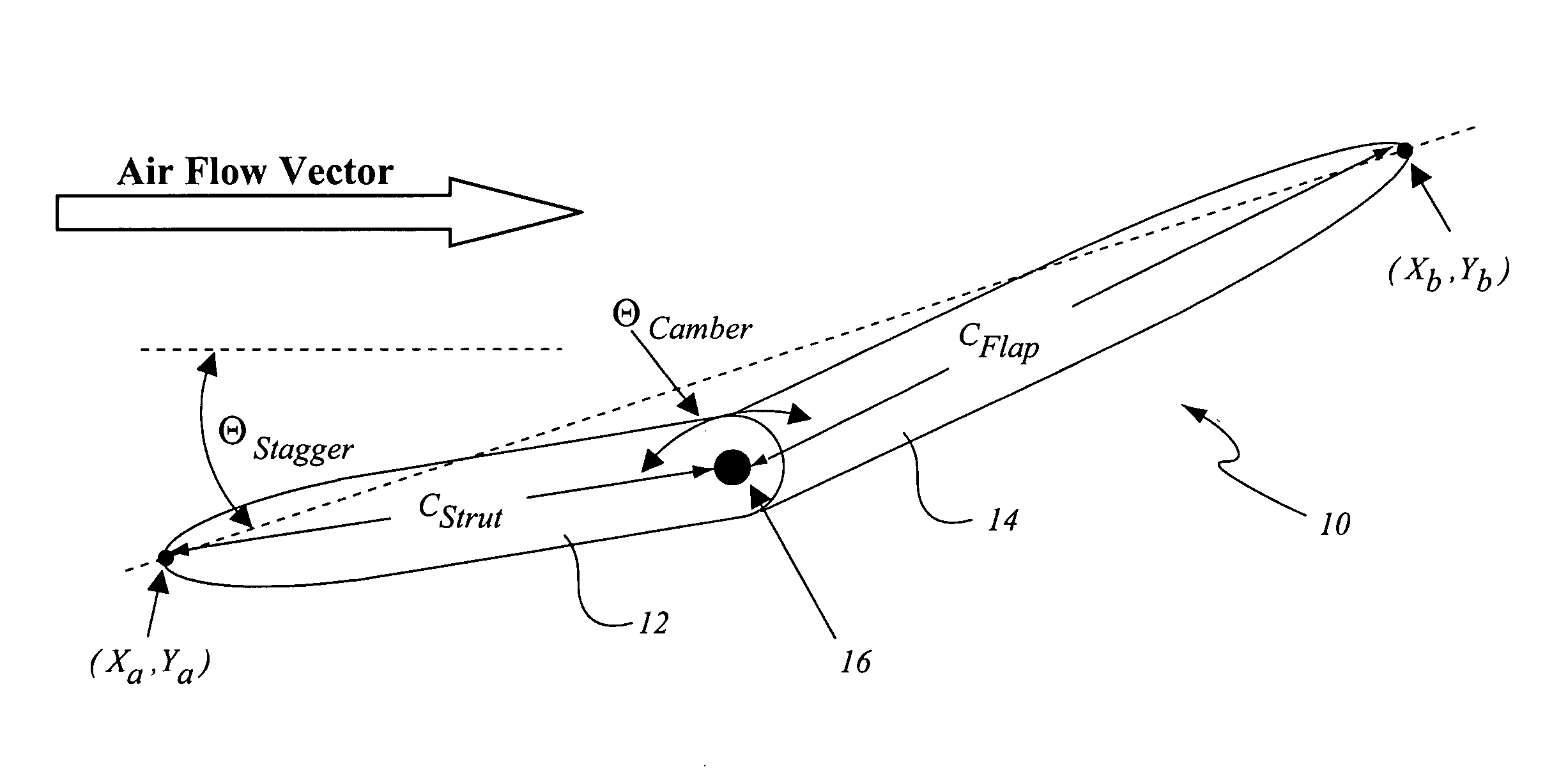
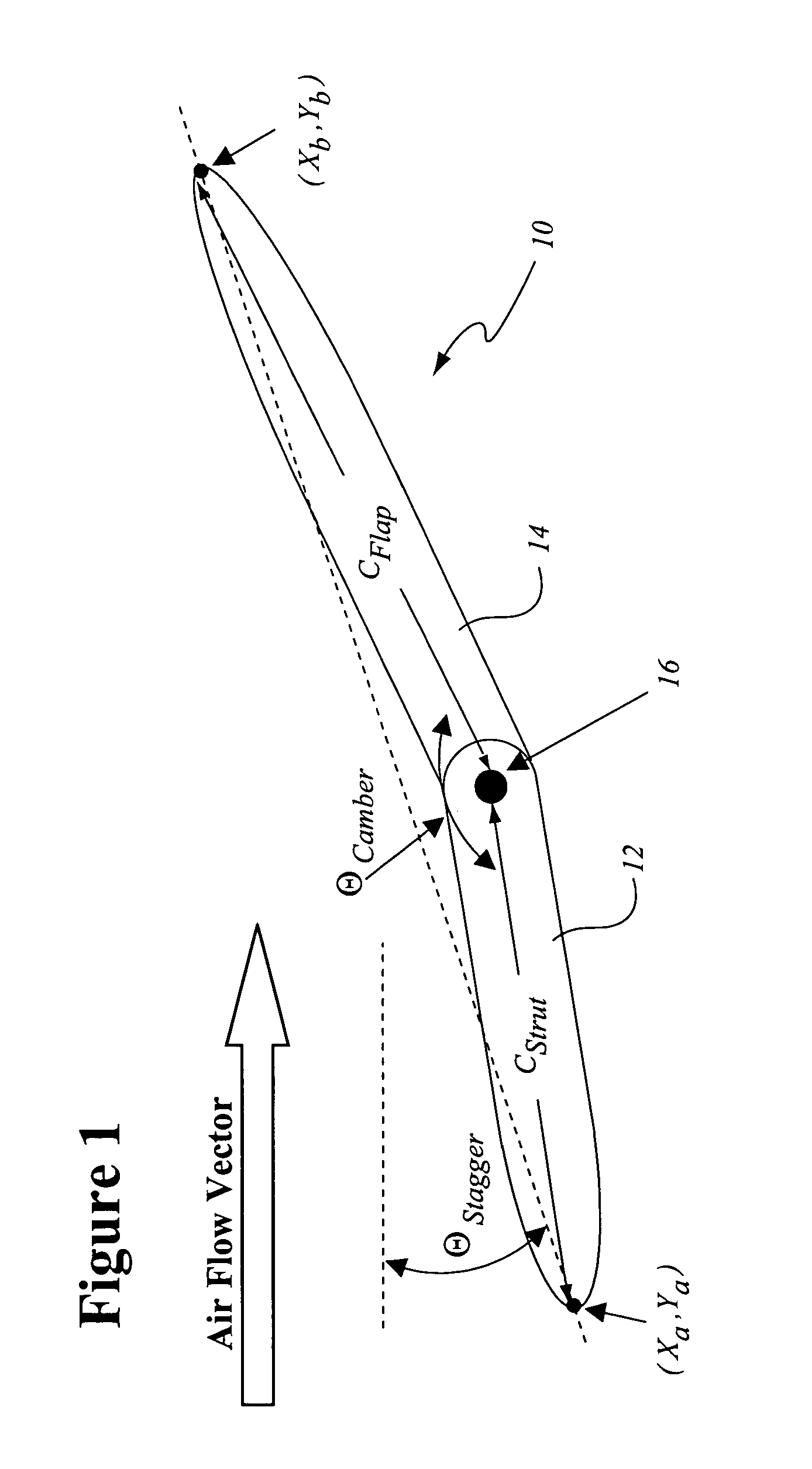
[0014]Referring to FIG. 1, and as noted above, the stagger angle ΘStagger is defined by the angle between the airflow velocity vector and a straight line which connects the leading and trailing edge of the interconnected airfoils in a chordwise direction. Camber (ΘCamber) is defined as the angle between the leading edge part 12 and trailing edge part 14.

[0015]The present invention provides aerodynamically efficient air flow management in axial flow-turbines by utilizing a variable stagger and camber airfoil 10. In an exemplary embodiment of the invention, this is accomplished by providing a two-piece airfoil including a leading edge part 12, hereinafter referred to as the strut, and a trailing edge part 14, hereinafter referred to as the flap, each of which is mounted to articulate about a common, radially oriented axis 16.

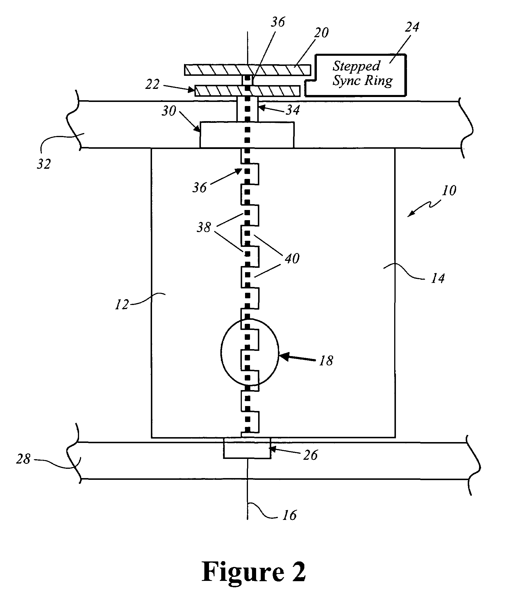
[0016]As illustrated in FIG. 2, in an exemplary embodiment of the invention, the strut and flap define an interlocking hinge 18. The strut 12 and flap 14 are resp...


PUM


Abstract

Aerodynamically efficient air flow management in axial flow-turbines is provided by utilizing a variable stagger and camber airfoil. In an exemplary embodiment of the invention, this is accomplished by providing a two-piece airfoil including a strut and a flap, each of which is mounted to articulate about a common, radially oriented axis. The strut and flap are respectively positioned by a strut gear and a flap gear, located at the radial end of the airfoil and, in an exemplary embodiment, are driven by a stepped synchronizing ring.

Description

BACKGROUND OF THE INVENTION[0001]The present invention relates to a mechanical method to create a variable stagger and camber airfoil.[0002]For power generation applications, limits on start time, grid demand response time, and maintenance factors create an environment where it is often advantageous to reduce the output of the gas turbine rather than shutting it down as demand is reduced. Axial flow industrial gas turbines modulate output levels by controlling the amount of air flow entering the compressor with inlet guide vanes.[0003]The conventional “Inlet Guide Vane” (IGV) is a single stage of articulated airfoils (about a radial axis) located in the front of the axial flow compressor. The maximum amount of air flow occurs when the IGV chord is aligned, or parallel, with the incoming air flow. This flow is reduced as the IGV stagger angle is rotated to a more aerodynamically closed position. For purposes of the disclosure, the stagger angle (ΘStagger) is defined as the angle betw...

Claims


Application Information

Patent Timeline
Patent Type & Authority Patents(United States)
IPC IPC(8): F01D9/04
CPCF04D29/563
Inventor MARTIN, NICHOLAS FRANCISSCHIRLE, STEVEN MARK
Owner GENERAL ELECTRIC CO
Why Eureka
Try Eureka