Unit for varying a temperature of a test piece and testing instrument incorporating same

a technology of test pieces and test instruments, which is applied in the direction of semiconductor/solid-state device testing/measurement, domestic cooling apparatus, furnaces, etc., can solve the problems of increasing the temperature of the test piece, enlarge the testing instrument, and take a long time to perform, so as to achieve the effect of more evenly distributed temperature distribution of the control face of the uni

Active Publication Date: 2006-10-03
ESPEC CORP
View PDF1 Cites 408 Cited by
  • Summary
  • Abstract
  • Description
  • Claims
  • Application Information

AI Technical Summary

Benefits of technology

[0019]In this present invention, the coolant supplied through the piping is jetted not in disorder but toward the target area within the cavity concentratively. The target area where the coolant is jetted is cooled much more than the other area where the coolant is not jetted. Proper selection of the target area enables to stabilize a temperature distribution of the control face and to readily control temperature as compared with some unit in the related art which supply the coolant in disorder within the cavity.
[0067]In such a testing instrument, all the branch pipes extending from the main pipe have the same length, so that the coolant which is supplied to the piping is distributed evenly thereto so as to be jetted from the ends thereof. In this arrangement, as for the unit, the coolant jetted from each branch pipe enables to cool substantially uniformly the annular portion, to which the heater is secured, from inside of the cavity. As a result, it is possible to make the temperature distribution of the control face of the unit more evenly. As a consequence, using such a testing instrument enables to perform the test more precisely.

Problems solved by technology

Such burn-in tests, though, take a lot of time since they require individual packaged integrated circuits to be mounted at testing instruments.
Further, the individual packaged integrated circuits have to be heated, resulting in troubles such as enlargement of testing instruments and increase of heat.
Still further, the integrated circuit which is discriminated as a defect by the burn-in tests has to be disposed of, resulting in a factor to cause useless process of package.
In such a structure, a system for cooling the unit 101 is extremely complicated, resulting in preventing stability and response of temperature control and / or reduction of volume and cost of apparatus.

Method used


Image

  • Unit for varying a temperature of a test piece and testing instrument incorporating same
  • Unit for varying a temperature of a test piece and testing instrument incorporating same
  • Unit for varying a temperature of a test piece and testing instrument incorporating same

Examples


Embodiment Construction

[0084]Now, a preferred embodiment of the present invention will be described below in detail, making reference to the accompanying drawings. A semiconductor wafer testing instrument and a unit for varying a temperature of a test piece incorporated in this testing instrument are illustrated in the description below.

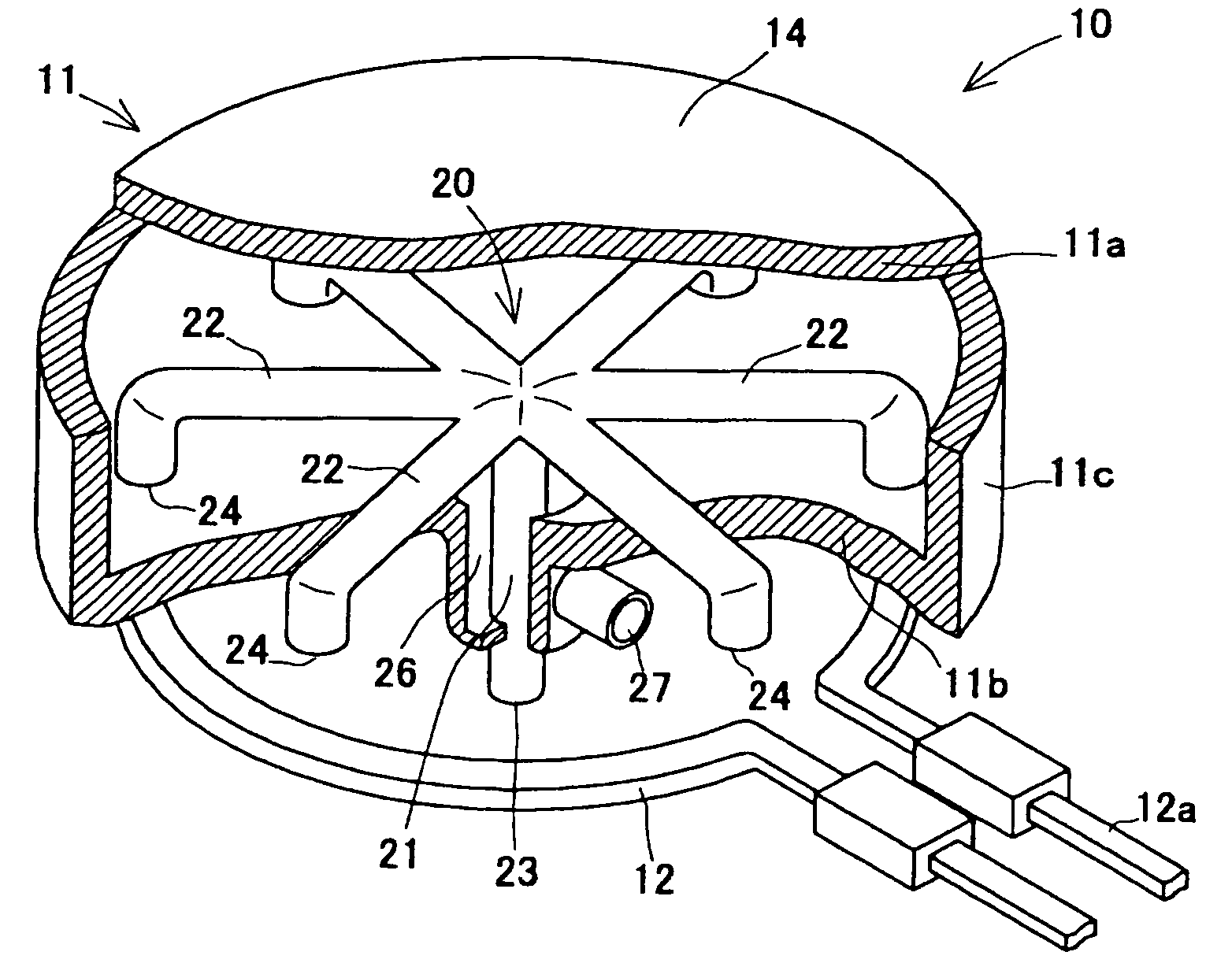
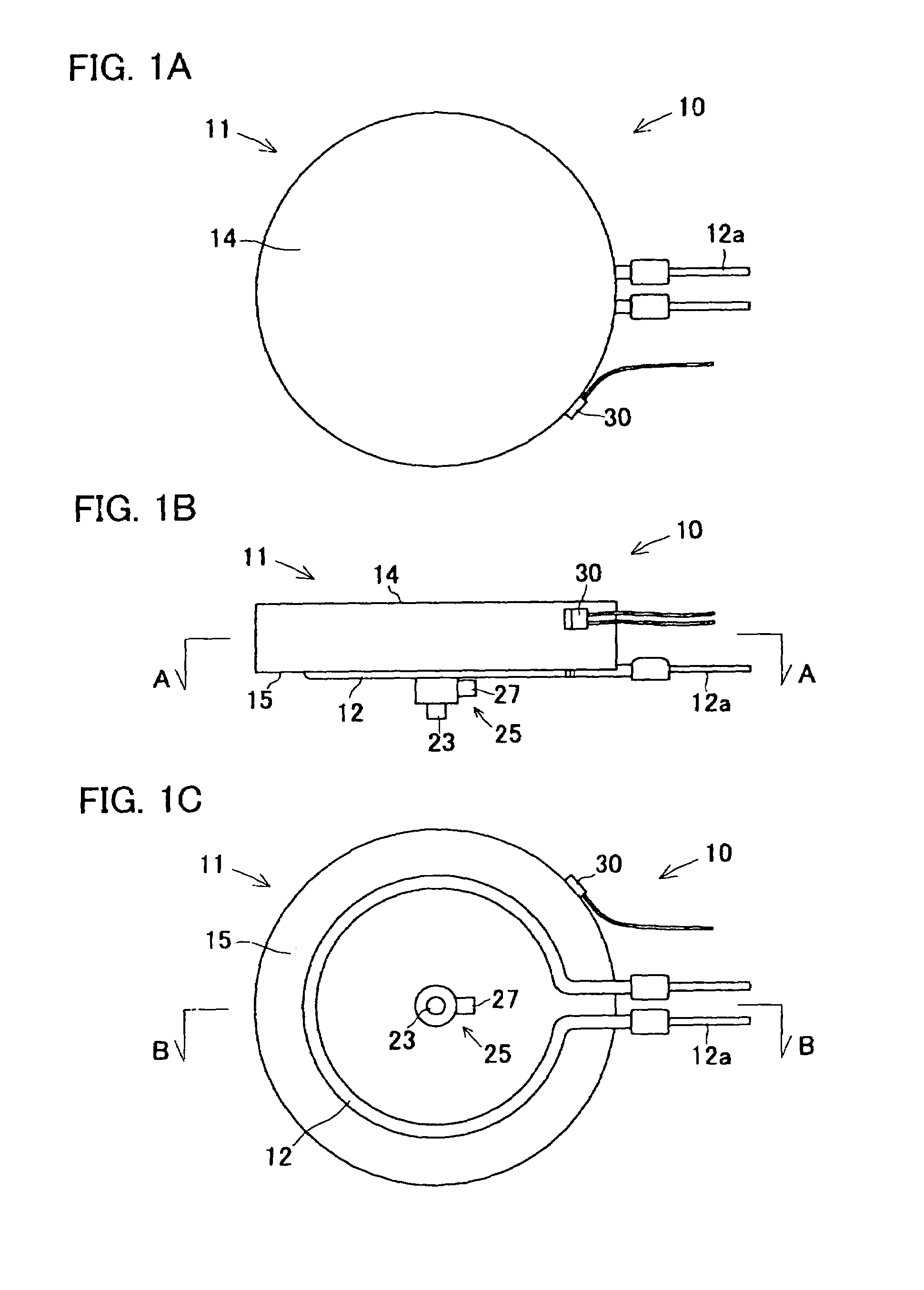
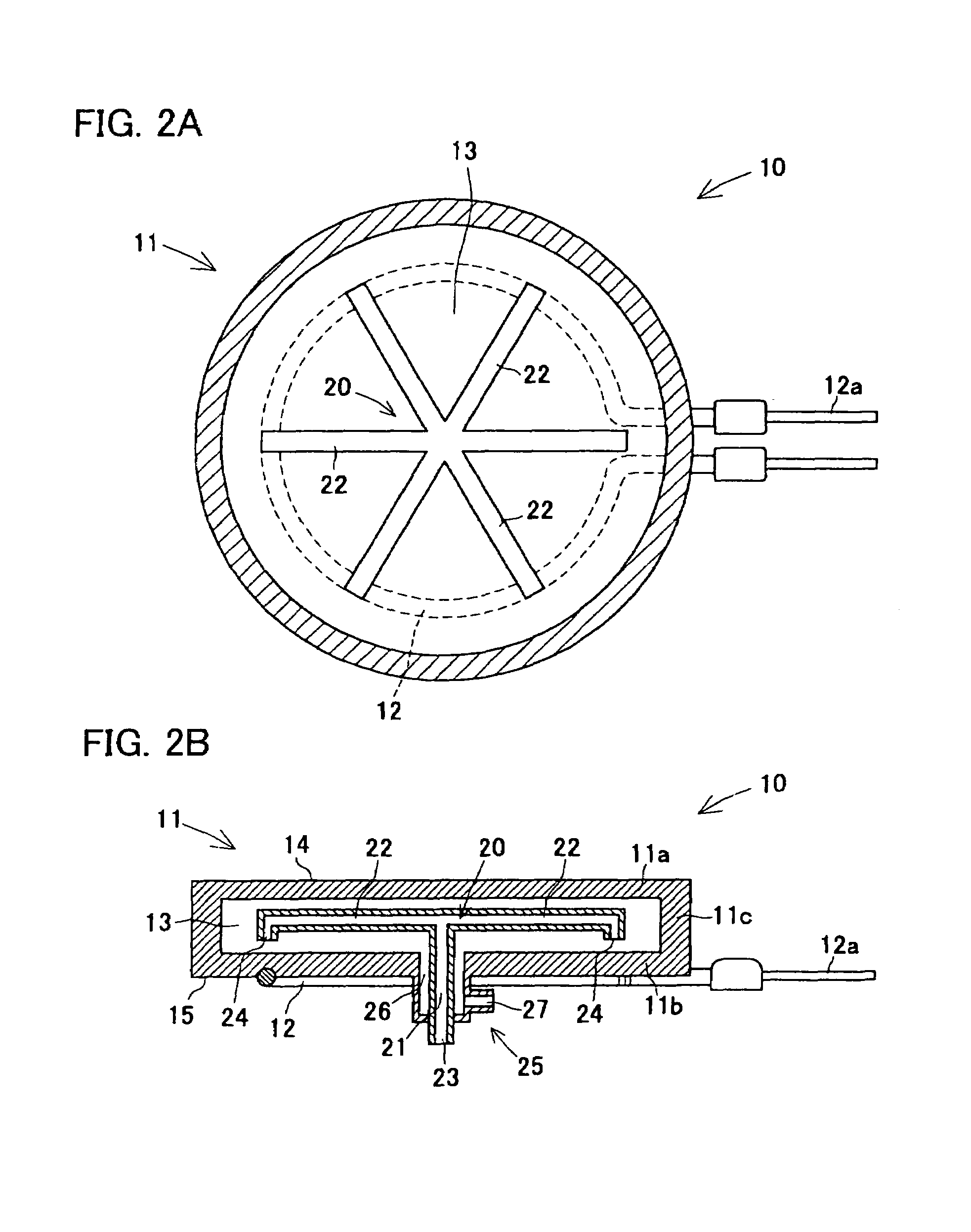
[0085]FIGS. 1A–1D show a plate-type unit 10 for varying a temperature of a test piece relating to the preferred embodiment. Describing in detail, FIG. 1A is a plan view of the plate-type unit 10, FIG. 1B is a front view thereof and FIG. 1C is a bottom view thereof. FIG. 2A is a cross-sectional view taken along line A—A of FIG. 1B, whereas FIG. 2B is a cross-sectional view taken along line B—B of FIG. 1C. FIG. 3 is a partly broken perspective view of the plate-type unit 10 shown in FIGS. 1A–1C.

[0086]The plate-type unit 10 of the preferred embodiment comprises a disc-shaped hollow plate 11 with a cavity 13 formed therein and having a heater 12. Describing sequentially, the p...


PUM

PropertyMeasurementUnit
temperatureaaaaaaaaaa
cylindrical shapeaaaaaaaaaa
surface areaaaaaaaaaaa

Abstract

A disc-type unit 10 adjusts temperature of a control face 14 by means of a heater 12 and coolant, with a hollow plate 11 to which the heater 12 is secured, a cavity 13 formed in the hollow plate 11 and a piping 20 for supplying the coolant to the cavity 13, the piping 20 opening in the cavity 13, and the coolant being jetted to a portion to which the heater 12 is secured or a portion in proximity thereto and which shows high temperature rise when energizing the heater 12.

Description

BACKGROUND OF THE INVENTION[0001]1. Field of the Invention[0002]The present invention relates to a unit for varying a temperature of a test piece by controlling a temperature of a control face. The present invention further relates to testing instruments incorporating the unit for environmental tests such as temperature and humidity chambers and for temperature tests of semiconductor wafers, electronic components and the like.[0003]2. Description of Related Art[0004]Temperature tests for electronic components such as integrated circuits are conventionally performed as burn-in tests. The burn-in tests of integrated circuits are done by separating several integrated circuits formed on a semiconductor wafer into individual bare dies and exposing each of the integrated circuits, which are packaged with sealing each separated bare die, in high temperature while turning electricity through the circuit. By means of the burn-in tests, it is enabled to reveal potential drawbacks in the integ...

Claims


Application Information

Patent Timeline
Patent Type & Authority Patents(United States)
IPC IPC(8): H05B3/68A21B2/00G01R31/26F25D9/00H01L21/00H01L21/66
CPCH01L21/67109H05B3/68
Inventor KURARA, HIRONOBUSONOBE, MUNEAKIENOMOTO, SHINICHI
Owner ESPEC CORP
Why Eureka
Try Eureka