Methods and apparatus for controlling a motor/generator

a technology of polyphase motors and generators, applied in the direction of motor/generator/converter stoppers, dynamo-electric converter control, instruments, etc., can solve the problems of reducing engine life, and affecting the operation of the engin

Active Publication Date: 2006-10-03
SAFRAN POWER USA LLC
View PDF16 Cites 40 Cited by
  • Summary
  • Abstract
  • Description
  • Claims
  • Application Information

AI Technical Summary

Benefits of technology

[0019]The methods and apparatus may further provide for: decreasing the peak amplitude of the second rotor excitation

Problems solved by technology

When the torque produced by the polyphase machine is too high at the ignition speed, then any number of mechanical linkages of the turbine engine may be overstressed.
Conversely, when the peak torque produced by the polyphase machine is too low at the ignition speed, it may take an excessive period of time to reach the start event.
An excessive torque or an insufficient torque condition at the ignition speed leads to undesirable results.
For example, overstressing mechanical linkages within the turbine engine reduces engine life and decreases the mean time between failures (MTBF).
Similarly, excessively long engine start conditions result in increased engine temperature (as it is typical that no air venting in the engine exists during startup), wasted fuel, reduced engine life, decreased MTBF, and false starts.
Unfortunately, optimizing the characteristics of the polyphase machine as a generator does not result in an optimum design of the polyphase machine as a motor.
However, this leads to undesirable results in connection with controlling the polyphase machine as a motor.
Alternatively, the proper peak torque at ignition characteristic might not be achievable in a polyphase machine that has been optimized as a generator.
Unfortunately, this may cause undesirable results during a generating mode (which is the more likely mode of o

Method used


Image

  • Methods and apparatus for controlling a motor/generator
  • Methods and apparatus for controlling a motor/generator
  • Methods and apparatus for controlling a motor/generator

Examples


Embodiment Construction

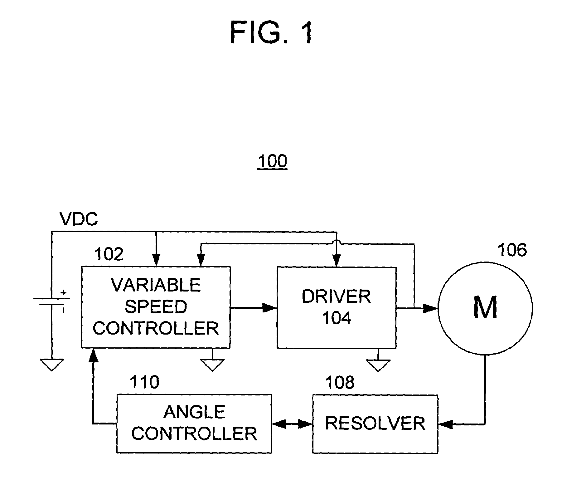
[0040]Referring now to the drawings, wherein like numerals indicate like elements, there is shown in FIG. 1 a block diagram illustrating one or more aspects of the present invention. For the purposes of brevity and clarity, the block diagram of FIG. 1 will be referred to, and described herein, as illustrating a system 100, it being understood, however, that the description may be readily applied to various aspects of one or more methods of the present invention with equal force.

[0041]The system 100 includes a source of DC power, a controller 102 (preferably a variable speed controller), and a driver circuit 104 that are operable to control and drive a polyphase machine 106. The system 100 also includes a resolver 108 and an angle controller 110 that are operable to measure the rotor position of the polyphase motor 106 and to provide feedback and angle correction signaling to the controller 102. Although the functional blocks for the controller 102, driver 104, resolver 108, and angl...


PUM


Abstract

Methods and apparatus provide for: commutating windings of a polyphase machine such that electromagnetic fields of stator and rotor phases of the polyphase machine produce at least one of motoring and generating torque; providing a first rotor excitation voltage having substantially no DC component when a rotational speed of the polyphase machine is below a predetermined value; and providing a second rotor excitation voltage having a DC component when the rotational speed of the polyphase machine is above the predetermined value.

Description

BACKGROUND OF THE INVENTION[0001]The present invention relates to methods and apparatus for controlling the torque / speed characteristics of a polyphase motor and / or generator.[0002]Polyphase machines, such as permanent magnet machines, synchronous machines, and wound rotor machines must be driven such that the windings thereof are energized as a function of the rotor position (and, thus, the rotor flux) in order to obtain driving torque from the machine (for motoring) and / or to obtain opposing torque to from the machine (for generating).[0003]Polyphase machines may be utilized as variable starter-generator machines for an engine, such as a turbine engine. A turbine engine is started by using the polyphase machine to apply torque to a main shaft of the turbine engine, while also providing fuel and other combustion elements to the engine. When the polyphase machine is controlled to produce a suitable torque verses speed characteristic, the turbine engine will start. At or some time af...

Claims


Application Information

Patent Timeline
IPC IPC(8): H02P1/18H02P27/05
CPCH02P23/10H02P25/02H02P27/05
Inventor SORKIN, LEV
Owner SAFRAN POWER USA LLC
Why Eureka
Try Eureka