
Wavelength-parallel polarization measurement systems and methods

Inactive Publication Date: 2006-10-03
PURDUE RES FOUND INC
View PDF6 Cites 24 Cited by
  • Summary
  • Abstract
  • Description
  • Claims
  • Application Information

AI Technical Summary

Benefits of technology

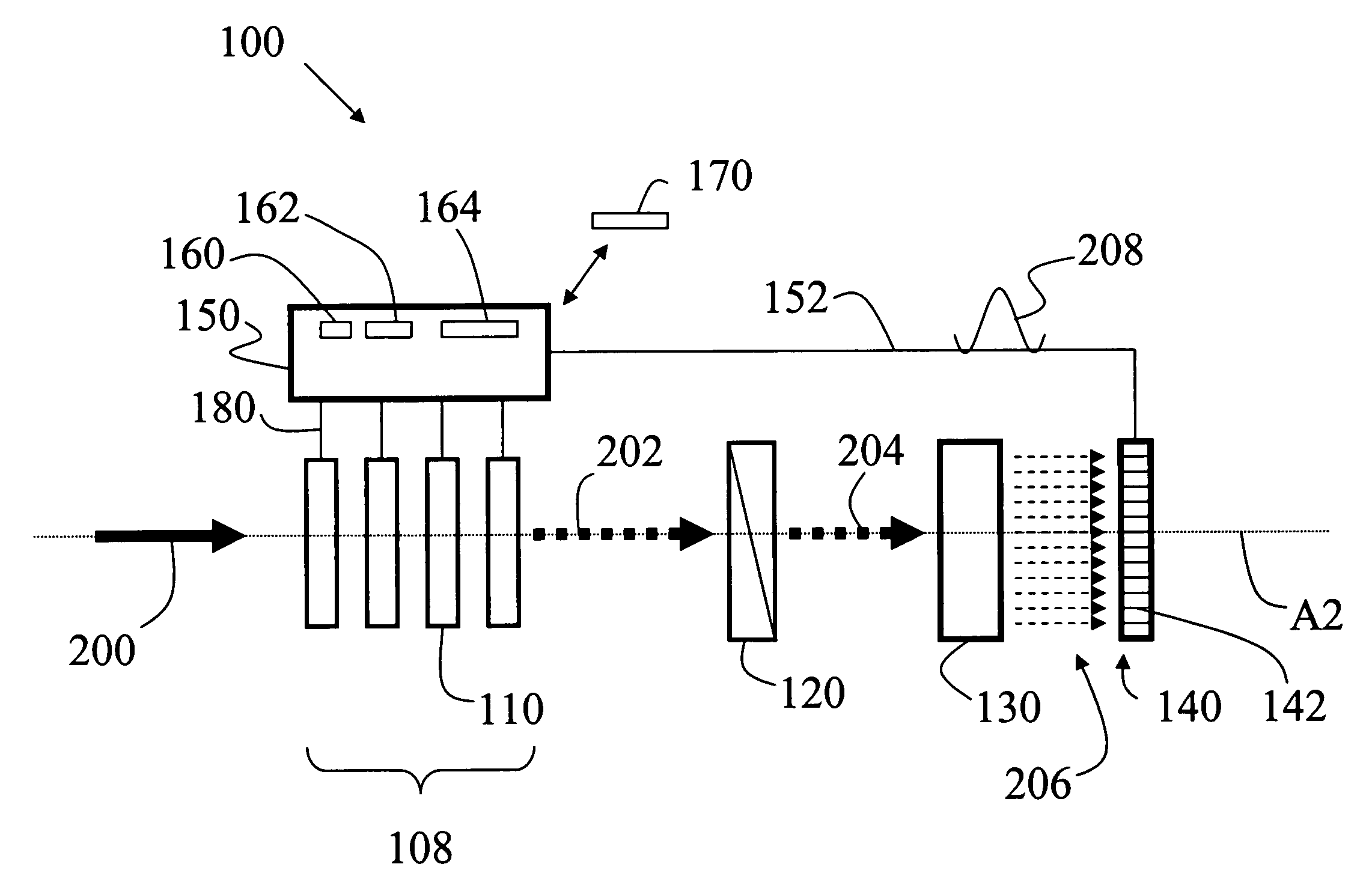
[0016]An aspect of the invention is a system for measuring the state of polarization (SOP) of wavelength components in a multi-wavelength input light beam. The system includes a set of two or more rapidly switchable waveplates selectively controllable to receive and operate on the input light beam to form a sequence of secondary light beams with different polarizations. The system includes a polarizer oriented to pass a select polarization and arranged to receive the secondary

Problems solved by technology

In particular, effects related to the polarization state of light (i.e., the orientation of the electric field vector associated with the lightwave signal) have recently emerged as key issues in extending the performance of lightwave systems.
This polarization scrambling results from very small and essentially random perturbations to the circular symmetry of long fiber optic cables arising both from the manufacturing process and from environmental perturbations.
On the other hand, any frequency-dependent polarization scrambling that degrades the orthogonality of adjacent channels leads to polarization cross-talk and impaired system performance.
Further, polarization scrambling in fiber optic propagation arises from random birefringence in the fiber.
These polarization-mode dispersion (PMD) effects lead to random signal fading and increased digital error rates.
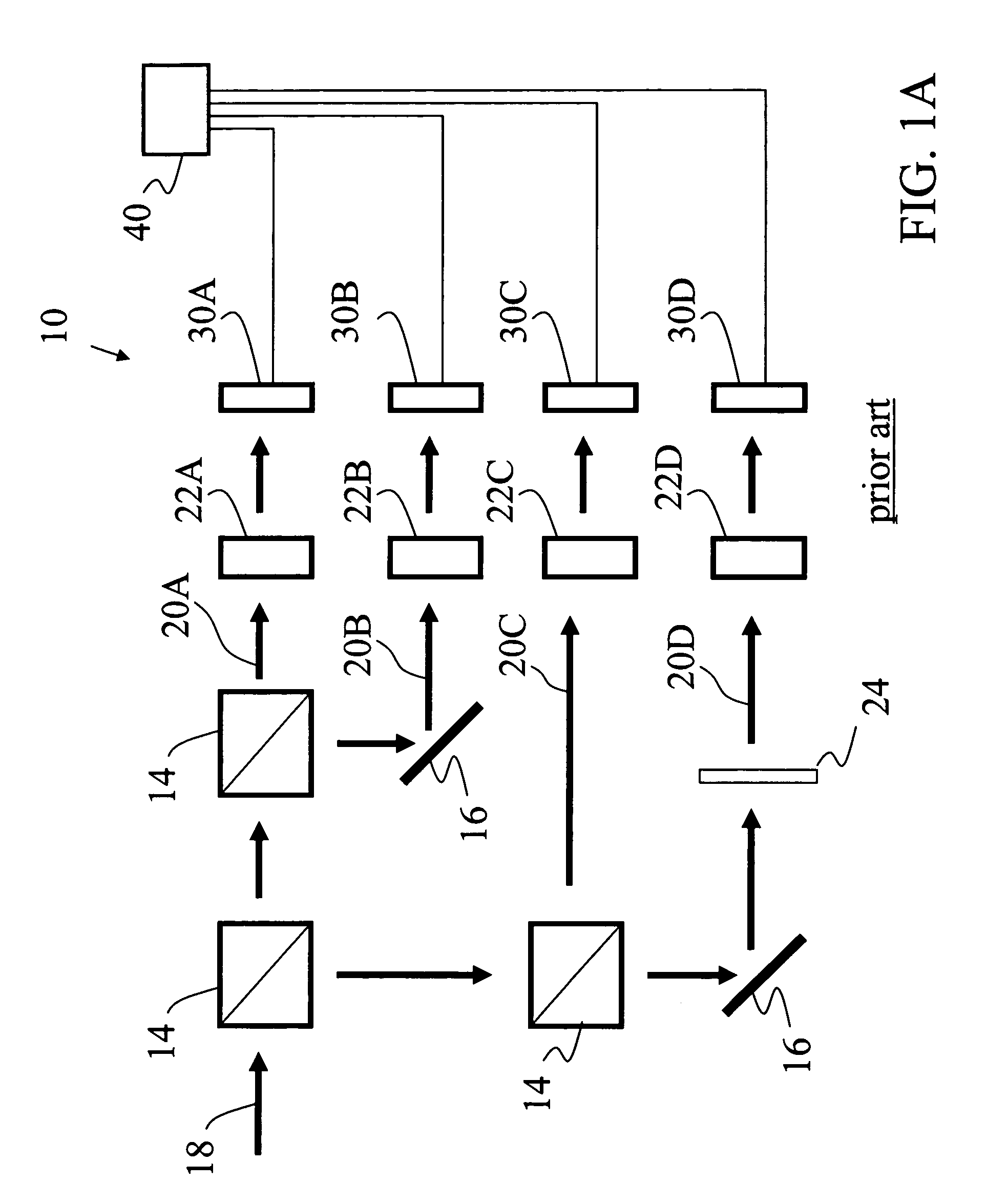
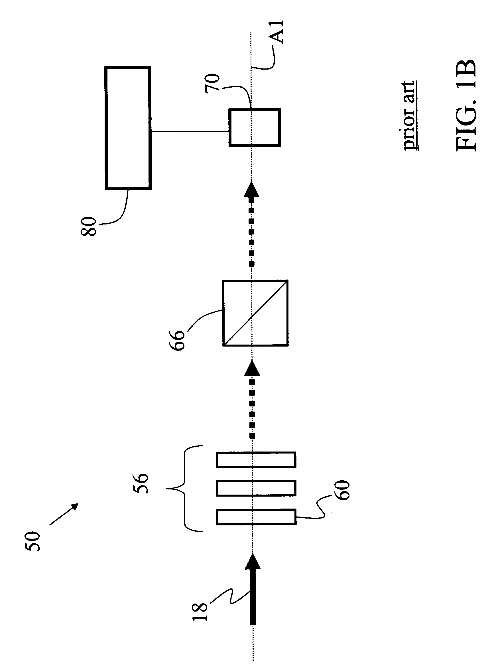
However, present day lightwave polarization measurement systems have significant shortcomings for WDM optical communications mainly because they can only measure one wavelength channel at a time.
While prior art polarization measurement systems such as those described above are suitable for measuring one wavelength channel at a time, they are unsuitable for lightwave transmission systems that employ multiple wavelengths.

Method used


Image

  • Wavelength-parallel polarization measurement systems and methods
  • Wavelength-parallel polarization measurement systems and methods
  • Wavelength-parallel polarization measurement systems and methods

Examples


Embodiment Construction

[0029]The present invention is a wavelength-parallel polarization measurement system capable of simultaneously and rapidly measuring the SOP for each wavelength component (i.e., wavelength channel) of a multi-wavelength light beam. In an example embodiment, the system performs the polarization measurements in about one millisecond or less. In an example embodiment, the system performs parallel polarization measurements of hundreds of wavelength channels with minimal total optical power requirements, e.g., on the order of a milliwatt or less. Because no mechanical movements are required to make a measurement, the system is capable of precise and repeatable measurements for each wavelength channel. In addition, the multi-wavelength input beam can be either a guided lightwave or a free-space light beam. The term “light beam” is used in the description below for the sake of clarity, and includes both a free-space light beam and a guided lightwave.

[0030]The ability to simultaneously meas...


PUM


Abstract

Systems and methods for measuring the state of polarization (SOP) for each wavelength channel in a multi-wavelength-channel light beam are disclosed. The system includes a set of two or more rapidly switchable waveplates switched to form a sequence of secondary light beams having different polarizations. A polarizer filters the set of secondary light beams, and a spectral dispersing element spatially divides the secondary light beams into their respective wavelength components. A detector array measures in parallel the intensity of the different wavelength components for each of the polarization-filtered light beams. A controller stores the intensity measurements and calculates the Stokes parameters for each wavelength component, thereby characterizing the SOP for all the wavelength channels of the multi-wavelength light beam.

Description

CLAIM OF PRIORITY[0001]This patent application claims priority of U.S. Provisional Patent Application No. 60 / 426,559, filed on Nov. 15, 2002, which application is hereby incorporated by reference.GOVERNMENT LICENSING RIGHTS[0002]The U.S. Government has a paid-up license in this invention and the right, in limited circumstances, to require the patent owner to license others on reasonable terms as provided for by the terms of Contract No. 0140682-ECS awarded by the National Science Foundation.CROSS-REFERENCE TO RELATED APPLICATIONS[0003]This application is related to U.S. patent application Ser. No. 10 / 705,159, entitled “Systems and Methods for Performing Wavelength-Parallel Polarization Measurements,” filed on the same day as the present application and hereby incorporated by reference.FIELD OF THE INVENTION[0004]The present invention relates to measuring the polarization of a light beam, and in particular, to systems and methods for measuring the polarization states of the different...

Claims


Application Information

Patent Timeline
IPC IPC(8): G01J4/00
CPCG01J3/447G01J4/04H04J14/02H04J14/06
Inventor WEINER, ANDREW M.WANG, XIANG
Owner PURDUE RES FOUND INC
Learn More