Laser level

a laser level and leveling technology, applied in the field of leveling instruments, can solve the problems of laser level being unable to be widely adopted laser level saving considerable time, laser level being unable to achieve widespread adoption by the general public, etc. cost barrier, the effect of reducing the cost of the necessary optical system

Inactive Publication Date: 2006-10-03
BLACK & DECKER INC
View PDF17 Cites 19 Cited by
  • Summary
  • Abstract
  • Description
  • Claims
  • Application Information

AI Technical Summary

Benefits of technology

[0004]The present invention relates to a laser level instrument. In one embodiment, the present invention employs a laser diode module as the laser source and optical system. The present invention can generate a level plane of light or a level line of light which can be a layout reference. Instead of defining an optical path by using expensive optical components and complex alignment procedures to manipulate the laser beam, the invention is capable of using relatively inexpensive optical components and novel alignment procedures to permit use of laser diode modules. In another feature, the invention provides a novel method where the existing laser beam output from a low cost laser diode module can be aligned to be perpendicular to the rotational axis of the laser level instrument. The method can dramatically decrease the cost of the necessary optical system used in the laser level. Thus the cost barrier which prevents the public from adopting the laser level as a general purpose tool is greatly reduced.

Problems solved by technology

Laser levels save considerable time during initial layout of a construction job compared to other tools such as beam levels, chalk lines, or torpedo levels.
Because these laser levels can typically cost thousands of dollars, only those who regularly land larger construction projects can justify purchasing a laser level.
Laser levels have not achieved widespread adoption by the general public despite the time savings because of their initial cost of ownership.
The expense can be attributed to the cost of suitable laser sources such as He-Neon laser and associated optical system used to manipulate the beam generated by the laser source.

Method used


Image

  • Laser level
  • Laser level
  • Laser level

Examples


Embodiment Construction

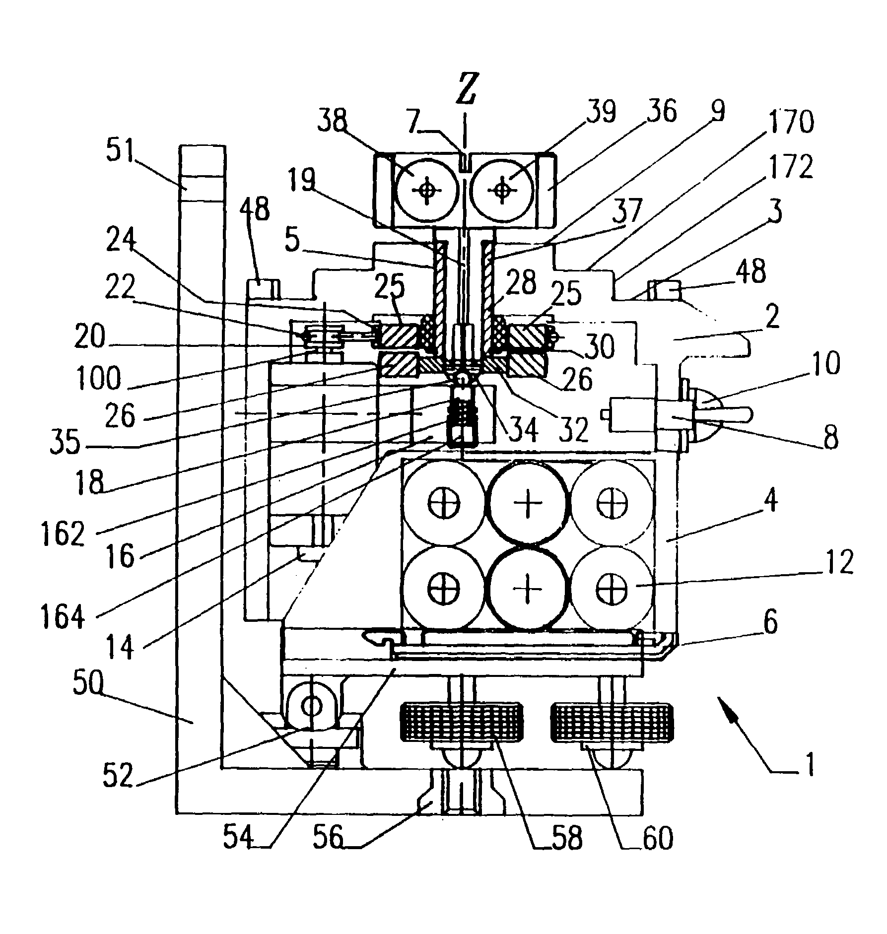
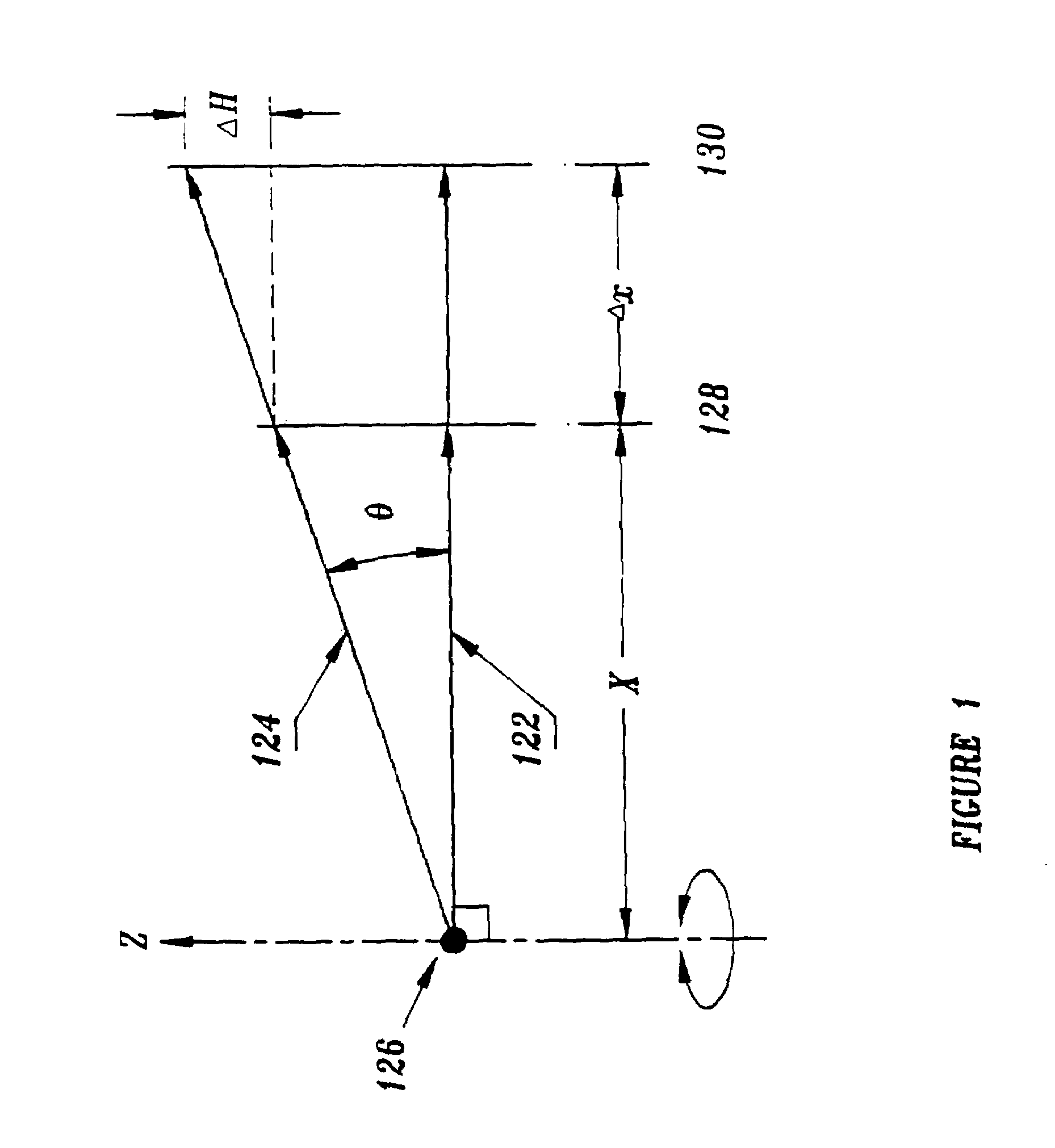
[0034]A laser level includes a laser beam that is rotated around a rotational axis. The optical system is extremely important to a laser level because the optical system is what manipulates the laser beam so that it can be aligned precisely perpendicular to the rotational axis of the laser level. It is important that the laser beam can be therefore aligned to be exactly perpendicular to the rotational axis. A properly aligned laser beam will create a level plane of the same height from a reference no matter how far or how close the target surface is from the laser level. When a laser beam that is not aligned to be perpendicular to the rotational axis, it will create a reference line which varies in height depending on how far or how close the target is away from the laser level instrument.

[0035]FIG. 1 illustrates a properly aligned laser beam 122 and an improperly aligned laser beam 124. Beam 122 is perpendicular to the Z-axis of rotation. Beam 122 is projected on two vertical targe...


PUM


Abstract

The present invention relates to laser leveling device suitable for construction. The present invention uses a standard low cost laser diode module as the laser source and optical system. A novel method is provided to align the non-collimated beam emitted from the standard low cost laser diode module so that it is perpendicular to the rotational axis of the laser level. The present invention describes a laser level which can be operated in four different modes: dot mode, line mode, oscillation mode and plane mode. Dot mode provides two level laser dots. Line mode provides a short bright level line. Oscillation mode provides a long bright reference line. Plane mode provides a level 360 degree reference plane. The invention also provides a structure which allows two vertical reference planes which are perpendicular to each other and perpendicular to the horizontal reference plane to be generated.

Description

[0001]This application is a continuation of application Ser. No. 08 / 806,102 now U.S. Pat. No. 5,754,582, filed on Feb. 25, 1997, which is a continuation of application Ser. No. 08 / 503,987 now abandoned, filed on Jul. 19, 1995, which is a continuation-in-part of application Ser. No. 08 / 415,960 now abandoned, filed on Apr. 3, 1995.BACKGROUND OF INVENTION[0002]The present invention relates generally to leveling instruments, and more particularly, relates to a laser leveling instrument capable of multiple modes of operation. The present invention is related to Disclosure Document No. 366475, entitled, Laser Level, filed on Dec. 8, 1994.[0003]Laser levels have been used in construction for many years. They typically seek to produce a plane of light for a reference for construction projects. Laser levels have been used for large scale construction projects like commercial excavating, laying foundations, and installing drop ceilings. Laser levels save considerable time during initial layou...

Claims


Application Information

Patent Timeline
Patent Type & Authority Patents(United States)
IPC IPC(8): H01S3/00G01C15/00
CPCG01C15/004
Inventor DONG, DAWEI
Owner BLACK & DECKER INC
Why Eureka
Try Eureka