Vibration generator for a soil compacting device

Inactive Publication Date: 2006-10-10
WACKER NEUSON SE
View PDF20 Cites 15 Cited by
  • Summary
  • Abstract
  • Description
  • Claims
  • Application Information

AI Technical Summary

Benefits of technology

[0008]The underlying object of the present invention is to indicate a vibration generator for soil compacting which retains on the one hand the advantageous design of what is known as the plate compactor, while on the other hand enabling forward and backward movement of the soil compacting device, as well as stationary compacting.

Problems solved by technology

Precisely on such cohesive soils, vibration plates having other designs can experience difficulty in moving forward.
However, this design has turned out to have the disadvantage that it is not possible, using reasonably economical means, to execute a continuous reversing, i.e. a traveling back and forth, of the vibration plate, with the possibility of compacting at a point, i.e., purposive compacting at one location without forward movement of the vibration plate.
However, in this case the imbalance shafts must be operated synchronously at double power consumption and with precise rotational speed, both for the stationary point compacting and for the transition from forward travel to backward travel, so that a considerable energy and control expense is required.

Method used


Image

  • Vibration generator for a soil compacting device
  • Vibration generator for a soil compacting device
  • Vibration generator for a soil compacting device

Examples


Embodiment Construction

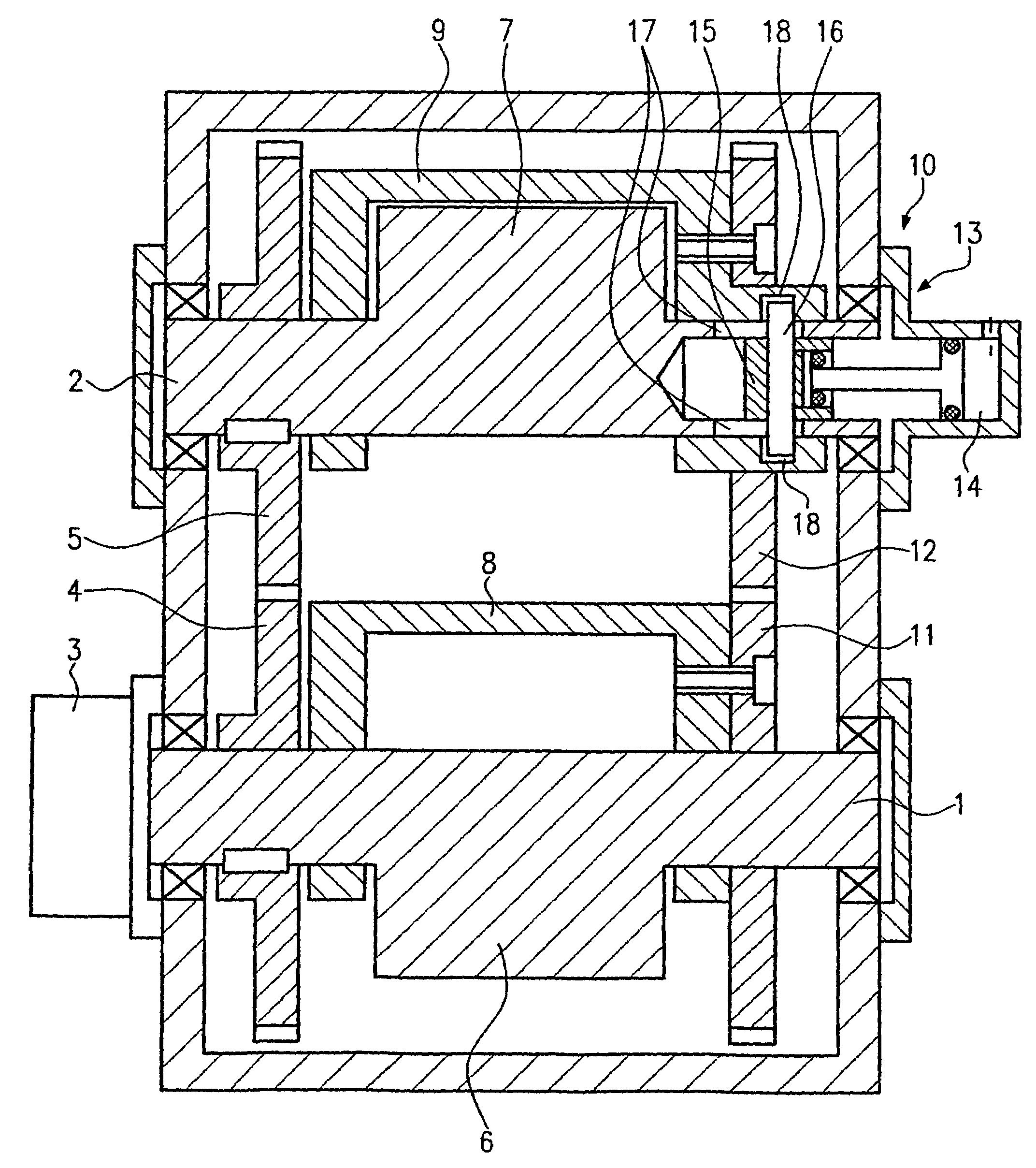
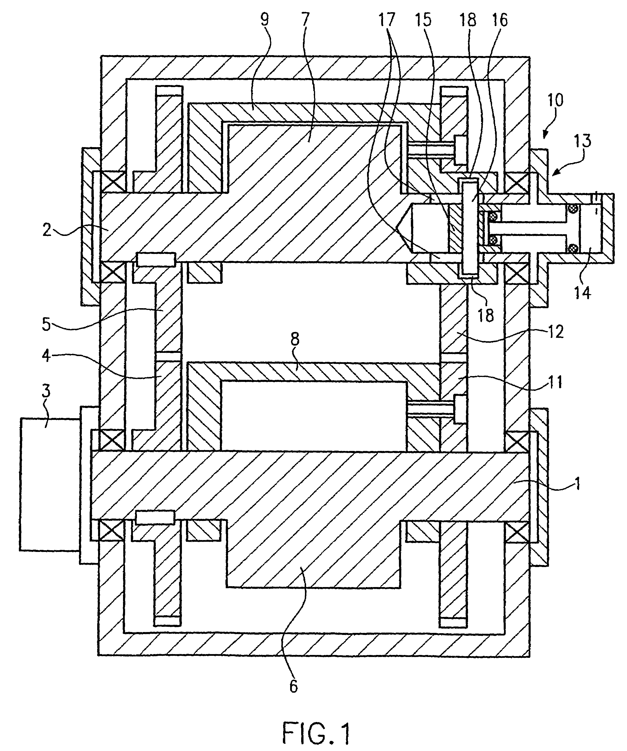
[0026]FIG. 1 shows a first specific embodiment of a vibration generator according to the present invention, having a first imbalance shaft 1 and a second imbalance shaft 2.

[0027]First imbalance shaft 1 is driven rotationally in a known manner by a drive 3 (not shown in more detail), for example a hydraulic motor or a coupling with an internal-combustion engine (not shown).

[0028]Via two toothed wheels 4 and 5, first imbalance shaft 1 is coupled with second imbalance shaft 2 in positively locking fashion, so as to be capable of rotation in the opposite direction. That is, first and second imbalance shafts 1, 2 rotate in a manner counter to one another.

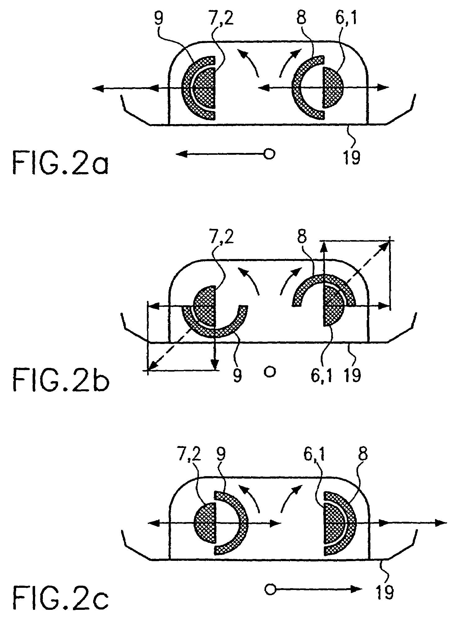
[0029]A first imbalance mass 6 is situated on first imbalance shaft 1, and second imbalance shaft 2 bears a first imbalance mass 7. First imbalance masses 6, 7 can be connected in one piece with imbalance shafts 1, 2 bearing them. It is also possible to fasten first imbalance masses 6, 7 to imbalance shafts 1, 2, for example using screws...


PUM


Abstract

The invention relates to vibration generator for a soil compacting device referred to as a towed vibrating device. The vibration generator has two parallels arranged unbalanced shafts that each support a fixed and a freely rotating unbalanced mass. An unbalance adjusting device enables the position of both freely rotating unbalanced masses to be adjusted in such a manner that, during a maximum unbalance action of one of the unbalanced shafts, the unbalance action on the other unbalanced shaft is minimized. The unbalance adjusting device can alter the position of the unbalanced masses whereby rendering possible a to-and-fro movement of the soil compacting device or a compaction when stationary.

Description

BACKGROUND OF THE INVENTION[0001]1. Field of the Invention[0002]The present invention relates to a vibration generator for a soil compacting device.[0003]2. Description of the Related Art[0004]For compacting soil, among others vibration plates known as “plate compactors” are known. In plate compactors, a vibration generator is seated in off-center fashion on a soil contact plate. The vibration generator is standardly a rotating imbalance shaft. The imbalance force, or centrifugal force, produced by the imbalance shaft pulls the soil contact plate (because of the off-center placement) upwards on one side and towards the front before the contact plate is pressed downward again, communicating the compacting energy to the soil. The vibration generator, which has a very simple construction, is thus able not only to produce the vibration required for the soil compacting, but also to move the soil contact plate forward.[0005]Plate compactor plates of this type have outstanding movement beh...

Claims


Application Information

Patent Timeline
IPC IPC(8): F16C33/10E01C19/30E02D7/18F16C33/00G05G1/00E02D3/074B06B1/16B06B1/18E01C19/34
CPCB06B1/162Y10T74/2157Y10T74/18552Y10T74/18344Y10T74/18024
Inventor RIEDL, FRANZ
Owner WACKER NEUSON SE
Why Eureka
Try Eureka