Dynamic seal with soft interface

a technology of dynamic sealing and soft interface, which is applied in the direction of engine components, mechanical equipment, cutting machines, etc., can solve the problems of essentially losing the time required to make a round trip for replacing a bit, affecting and affecting the sealing performance. , to achieve the effect of improving the life of the bi

Inactive Publication Date: 2006-10-10
SMITH INT INC
View PDF75 Cites 29 Cited by
  • Summary
  • Abstract
  • Description
  • Claims
  • Application Information

AI Technical Summary

Benefits of technology

[0021]The seal assemblies described herein offer the potential for enhanced seal and bit life as compared to conventional elastomeric seals. Further, certain embodiments offer substantial axial space savings such that the seal assembly may be employed in even relatively small bit sizes. Further still, providing a seal assembly as herein described creates a dynamic seal where the components are self adapting to form and maintain dynamic sealing faces as the dynamic and kinematic conditions affecting the rotatable components undergo substantial changes, and as the relative geometric positions between the various seal components and the pressures exerted between them change during use.

Problems solved by technology

When cuttings are conveyed into the seal gland, they tend to adhere to the gland and / or seal component surfaces and may cause deformation, damage and / or slippage of the seal components.
Moreover, the cuttings can accelerate abrasive wear of all seal components and of the bearing surfaces.
The amount of time required to make a round trip for replacing a bit is essentially lost from drilling operations.
As is thus obvious, this process, known as a “trip” of the drill string, requires considerable time, effort and expense.
Importantly, the seals must function for substantial periods under extremely harsh downhole conditions.
One cause of bit failure arises from the severe wear or damage that may occur to the bearings on which the cone cutters are mounted.
These bearings can be friction bearings (also referred to as journal bearings) or roller type bearings, and are typically subjected to high drilling loads, high hydrostatic pressures in the hole being drilled, and high temperatures.
The service life of bits equipped with such elastomeric seals is generally limited by the ability of the elastomeric seal material to withstand the different temperature and pressure conditions at each dynamic and static seal surface.
Although such seal construction provides improved wear resistance at the dynamic seal surface when compared to single-elastomer seals, the amount of wear resistance and seal life that is provided is still limited by the properties inherent in the elastomeric materials.
Such metal-to-metal seals were developed in order to increase the working life of the bearings given that the failure of conventional elastomeric O-rings was one of the most frequent causes of bit failure, such failure manifesting itself in a loss or breakage of inserts on the rolling cone cutters, and even loss of entire cones.
Relatively large diameter bits that included correspondingly large cone cutters could accommodate such multiple-component, metal-to-metal seal assemblies; however, in smaller sized bits, such as 8.5 inches in diameter and below, which account for a very large portion of bits made and employed, such space was hardly available, meaning that the bit designer was forced to accept design compromises.
For example, the designer could employ the use of an elastomeric, o-ring seal with its relatively shorter life, or use a metal-to-metal seal with smaller than desired energizers due to the space limitations, or he could provide the space in the cone required for the desired metal-to-metal seal assembly, but at the expense of cone and leg strength due to the removal of additional cone steel and the relocation of bearings as required to house and retain the components.
Manufacturing such seals is time consuming and expensive.
In many conventional designs, a lack of flatness in the engaging surfaces, misalignment of the engaging surfaces upon assembly or later use, and similar irregularities can be detrimental to seal life and thus to bit life.

Method used


Image

  • Dynamic seal with soft interface
  • Dynamic seal with soft interface
  • Dynamic seal with soft interface

Examples


Embodiment Construction

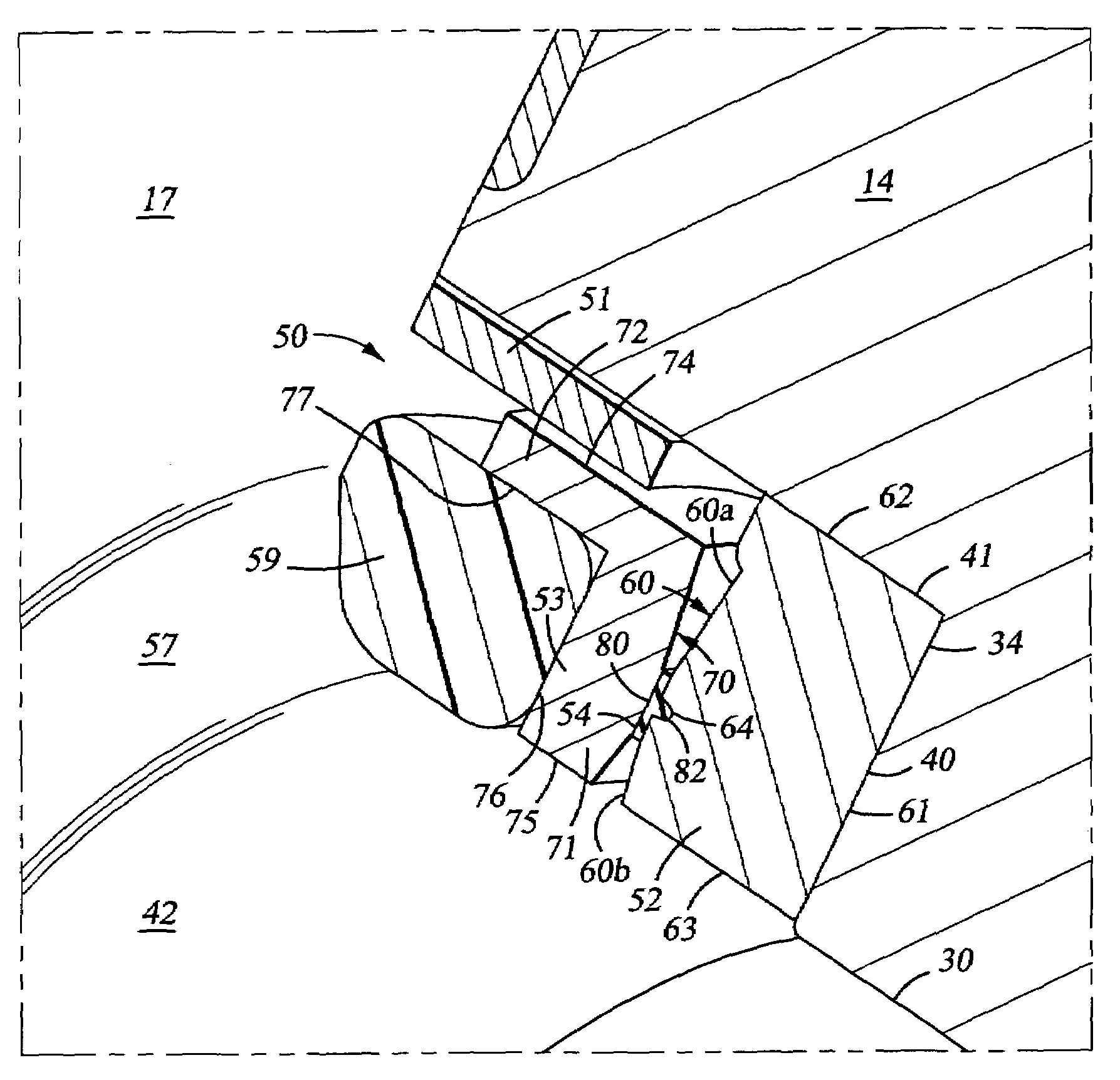
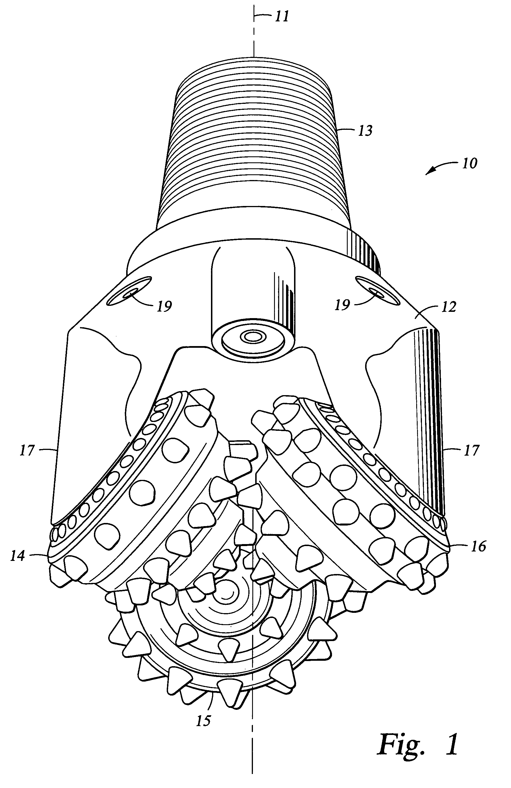
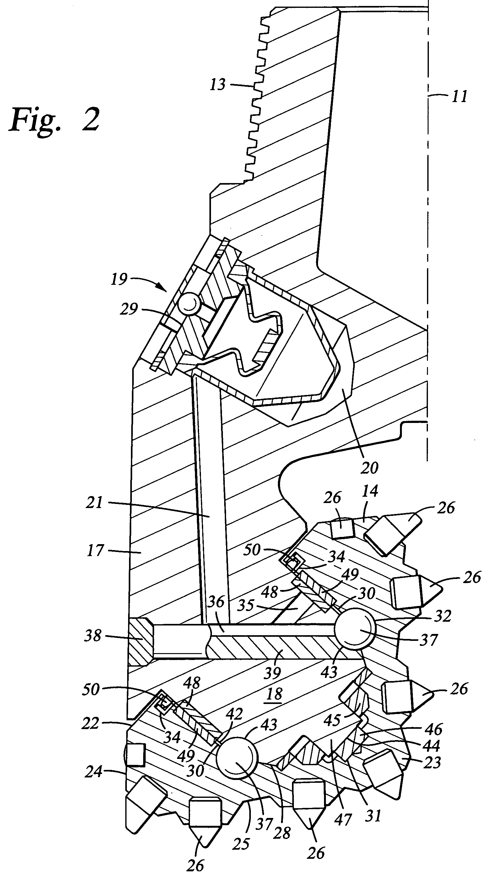
[0019]Described herein is a seal assembly for dynamically sealing between rotatable members, such as a rolling cone of a rock bit. One preferred seal assembly includes a first relatively soft but non elastomeric seal ring. The assembly further includes a second seal ring having a facing surface engaging the first seal ring as the two members rotate with respect to one another. The facing surface of the second seal ring is made of a material much harder than the first material, preferably, a material that is at least two or more times harder than the material of the first seal ring. In certain embodiments, the first seal ring is metallic, such as a ring made from tin, copper, aluminum, magnesium, lead and alloys thereof. The relatively soft seal ring may also be made of non metallic materials such as nylon-zytel, acetal and polypropylene. Preferred materials for the facing surface of the second seal ring include hardened steel and tungsten carbide. In certain embodiments, the seal as...


PUM

PropertyMeasurementUnit
diameteraaaaaaaaaa
hardnessaaaaaaaaaa
resilientaaaaaaaaaa

Abstract

A device and method for dynamically sealing between rotatable members such as a rolling cone of a rock bit. The assembly includes a seal ring having a facing surface of a relatively hard material, such as hardened steel or tungsten carbide, and a second seal ring of a softer material, the softer material being harder, however, than typical elastomers. Suitable materials for the relatively soft seal ring include tin, copper, aluminum, magnesium, lead and alloys thereof, as well as non-metallic materials such as nylon-zytel, acetal, and polypropylene. The relatively soft seal ring may be affixed to a third seal ring or maybe affixed directly to the cone steel, for example. The seal assembly provides potential for longer life relative to elastomeric seals and requires less axial space along the journal surfaces than certain conventional metal seal assemblies.

Description

CROSS-REFERENCE TO RELATED APPLICATIONS[0001]Not Applicable.STATEMENT REGARDING FEDERALLY SPONSORED RESEARCH OR DEVELOPMENT[0002]Not Applicable.BACKGROUND OF THE INVENTION[0003]1. Field of the Invention[0004]The invention relates generally to seal assemblies for sealing between a rotating and a static member. In one aspect, and more particularly, the invention relates to seals for rolling cone bits used to drill a borehole for the ultimate recovery of oil, gas or minerals. Still more particularly, the invention relates to dynamic seals of multi-material construction that are employed to protect the bearing surfaces between the rolling cone cutters and the journal shafts on which they rotate.[0005]2. Description of the Related Art[0006]An earth-boring drill bit is typically mounted on the lower end of a drill string and is rotated by revolving the drill string at the surface or by actuation of downhole motors or turbines, or by both methods. With weight applied to the drill string, t...

Claims


Application Information

Patent Timeline
Patent Type & Authority Patents(United States)
IPC IPC(8): E21B10/22E21B10/25F16J15/34
CPCE21B10/25F16J15/344E21B10/22
Inventor YONG, ZHOUDERIMANOCZY, DEAN PETER
Owner SMITH INT INC
Why Eureka
Try Eureka