
Axle unit for driving wheel

a technology for axles and driving wheels, applied in the direction of bearing units, rigid support, couplings, etc., can solve the problems of uneven unevenness, easy over-excuse of surface pressure acting on seal members, and generation of uncomfortable noises and vibrations

Inactive Publication Date: 2006-10-10
NSK LTD
View PDF22 Cites 19 Cited by
  • Summary
  • Abstract
  • Description
  • Claims
  • Application Information

AI Technical Summary

Benefits of technology

This design enhances the durability and reliability of the axle unit, reducing noise and vibrations, improving sealing performance, and maintaining riding comfort and power efficiency.

Problems solved by technology

Firstly, when the end face of the caulk portion 29 and the outer end face of the housing portion 11 are contacted directly with each other, the surface pressure of the contact portion increases. Accordingly, one or both of the end face of the caulk portion 29 and the outer end face of the housing portion 11 is or are exhausted (that is, plastically deformed and thereby dented). This increases a clearance between the end face of the caulk portion 29 and the outer end face of the housing portion 11. Then, as the vehicle runs, the hub 6a is shifted (shaken) in the axial direction with respect to the drive shaft member 31, which gives rise to generation of uncomfortable noises and vibrations.
Also, when the end face of the caulk portion 29 is contacted with the O ring 37, the width (in the diameter direction) of the circular-ring-shaped contact portion is narrow, which makes it difficult to secure the sealing performance between them.
Further, when the calk portion 29 is disposed opposite a seal member, and the portion of the seal member opposed to the caulk portion 29 is flat, surface pressure acting on the seal member easily becomes excessive and uneven.
This makes it difficult to secure not only the durability of the seal member, but also the sealing performance by the seal member.

Method used


Image

  • Axle unit for driving wheel
  • Axle unit for driving wheel
  • Axle unit for driving wheel

Examples


first embodiment

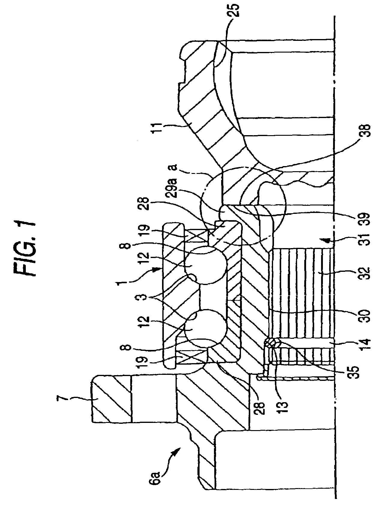
[0022]FIG. 1 is a section view of a half section of a drive-wheel axle unit according to the invention;

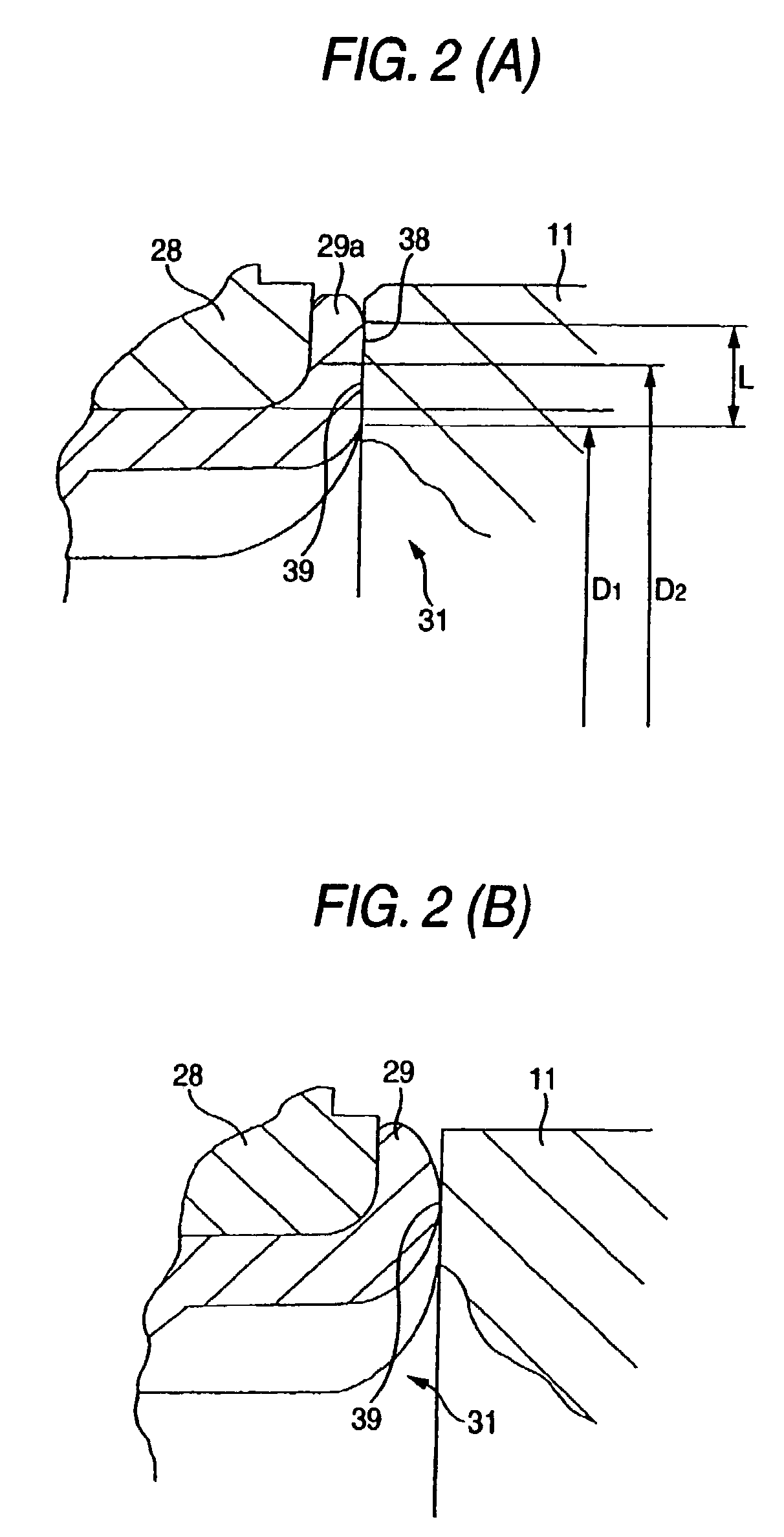
[0023]FIG. 2 (A) is an enlarged view of the a portion shown in FIG. 1, while FIG. 2 (B) shows a structure different from the invention for comparison, and is an enlarged view of a portion thereof corresponding to FIG. 2 (A);

second embodiment

[0024]FIG. 3 is a section view of a half section of a drive-wheel axle unit according to the invention;

[0025]FIG. 4 (A) is an enlarged view of the b portion shown in FIG. 3, while FIG. 4 (B) shows a structure different from the invention for comparison and is an enlarged view of a portion thereof corresponding to FIG. 4 (A);

third embodiment

[0026]FIG. 5 is a section view of a half section of a drive-wheel axle unit according to the invention;

[0027]FIG. 6 (A) is an enlarged view of the c portion shown in FIG. 5, while FIG. 6 (B) shows a structure different from the invention for comparison and is an enlarged view of a portion thereof corresponding to FIG. 6 (A);


PUM


Abstract

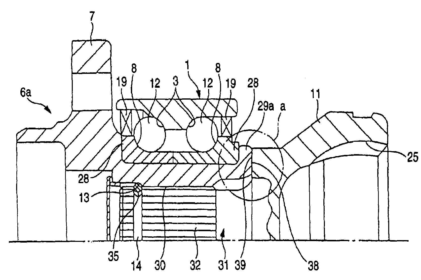
A drive-wheel axle unit which prevents the mutual contact portion between a caulk portion (29a) of a hub (6a) and an outer-end face (39) of a housing portion (11) of a drive shaft member (31) from being exhausted, thereby preventing the occurrence of shaky motion, strange sounds and vibrations for a long period of time. A flat surface (38) is formed in the end face of the caulk portion (29a), and is contacted over a large area with the outer end face (39), which makes it possible to reduce the contact surface pressure in the mutual contact portion between the flat surface (38) and outer end face (39).

Description

TECHNICAL FIELD[0001]An axle unit for a driving wheel according to the present invention is a so called fourth-generation hub unit in which a constant velocity joint and a hub unit are removably connected together as an integral body; and, the axle unit is used not only to support the drive wheels (front wheels of an FF car (a front-engine front-wheel-drive car, the rear wheels of an FR car (a front-engine rear-wheel-drive car) and an RR car (a rear-engine rear-wheel-drive car), and a 4WD car (a four-wheel-drive car)) supported on the independent suspension in such a manner that the drive wheels can be rotated with respect to the suspension, but also to drive or rotate these drive wheels.BACKGROUND ART[0002]To support the wheels so as to be rotatable with respect to the suspension, there are used various axle units in which outer and inner rings are rotatably combined together through rolling elements. An axle unit for a driving wheel—which is used not only to support the drive whee...

Claims


Application Information

Patent Timeline
Patent Type & Authority Patents(United States)
IPC IPC(8): B60B27/00B60K17/30F16C13/00B60B35/18B60B35/14F16C19/18F16C35/063F16D3/20
CPCB60B27/00F16D3/223F16C33/768F16C19/186F16D2003/22326F16C19/184F16C19/527F16C35/063F16C35/073F16C43/04F16C2326/02
Inventor KAYAMA, SHIGEOKIOUCHI, HIDEO
Owner NSK LTD
Learn More