Shunt system including a flow control device for controlling the flow of cerebrospinal fluid out of a brain ventricle

a flow control and cerebrospinal fluid technology, applied in the field of shunt systems, can solve the problems of unfavorable patient safety, unfavorable patient comfort, and difficulty in maintaining the implanted valve, and achieve the effect of reducing the risk of infection

Active Publication Date: 2006-10-10
INTEGRA LIFESCI SWITZERLAND SARL
View PDF34 Cites 71 Cited by
  • Summary
  • Abstract
  • Description
  • Claims
  • Application Information

AI Technical Summary

Problems solved by technology

However, due to the elastomeric properties of the diaphragm material, maintenance of the implanted valve may be required.
Further, flow rate adjustment of the Hakim et al. device after implantation may require a surgical procedure.
Although the Watanabe device permits flow rate control palpably through the scalp and thus, without surgical intervention, patient and / or physician attention to the valve settings is required.
Effective fluid flow rate control is particularly important since overdrainage of cerebrospinal fluid can result in dangerous conditions, including subdural hematoma.
However, noise associated with the use of such multiple weights may be objectionable.

Method used


Image

  • Shunt system including a flow control device for controlling the flow of cerebrospinal fluid out of a brain ventricle
  • Shunt system including a flow control device for controlling the flow of cerebrospinal fluid out of a brain ventricle
  • Shunt system including a flow control device for controlling the flow of cerebrospinal fluid out of a brain ventricle

Examples


Embodiment Construction

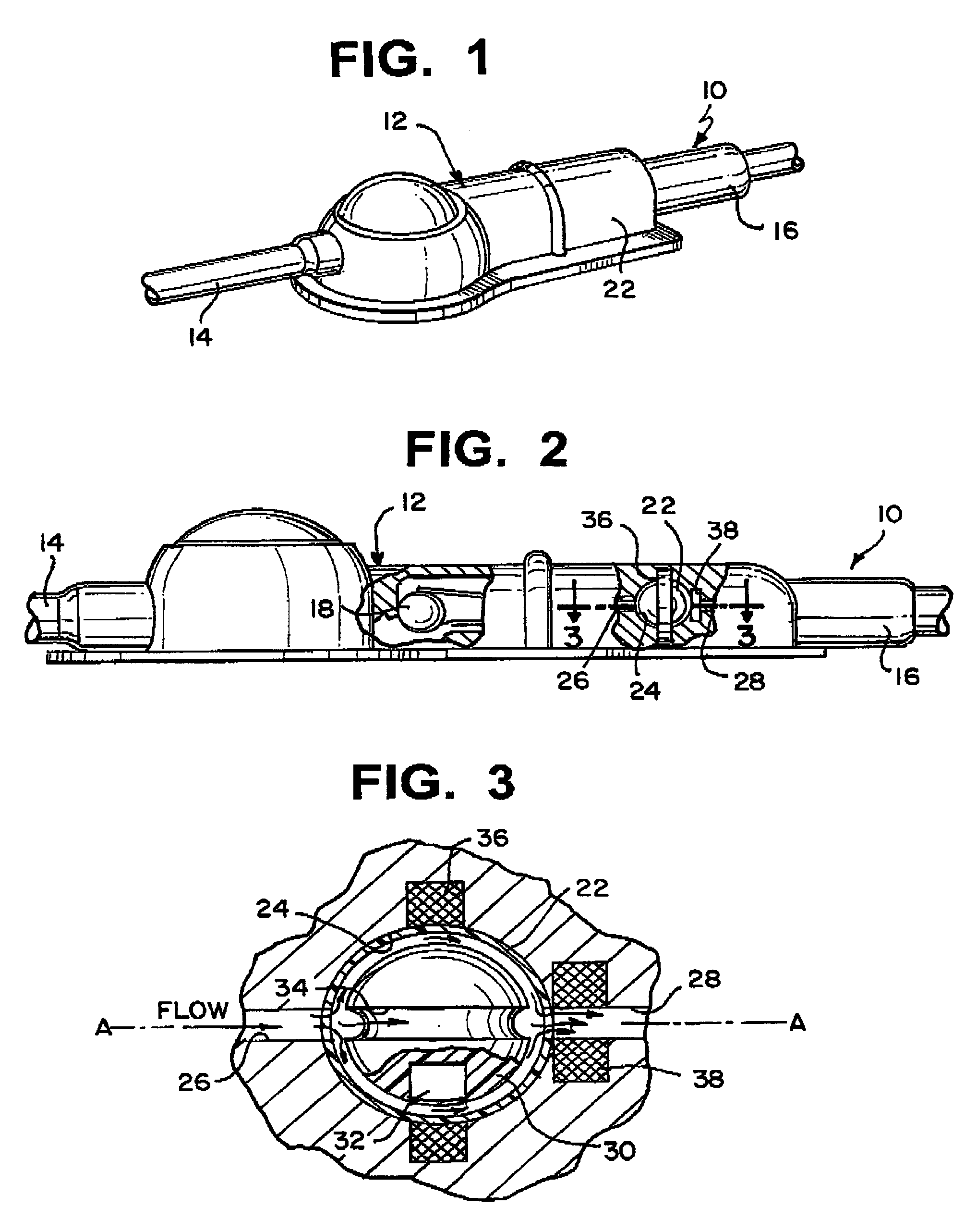
[0019]Referring now to FIGS. 1–4, a system 10 for limiting the flow of a fluid from a first region of a patient's body to a second region is illustrated. The system includes a housing 12 having an inlet 14 and an outlet 16. A one-way valve 18 is disposed within housing 12. The spring bias of the one-way valve is preferably programmable, as is taught in U.S. Pat. Nos. 4,615,691 and 4,772,257 to Hakim et al. and U.S. Pat. No. 5,928,182 to Kraus et al., the disclosures of which are hereby incorporated by reference in their entirety.

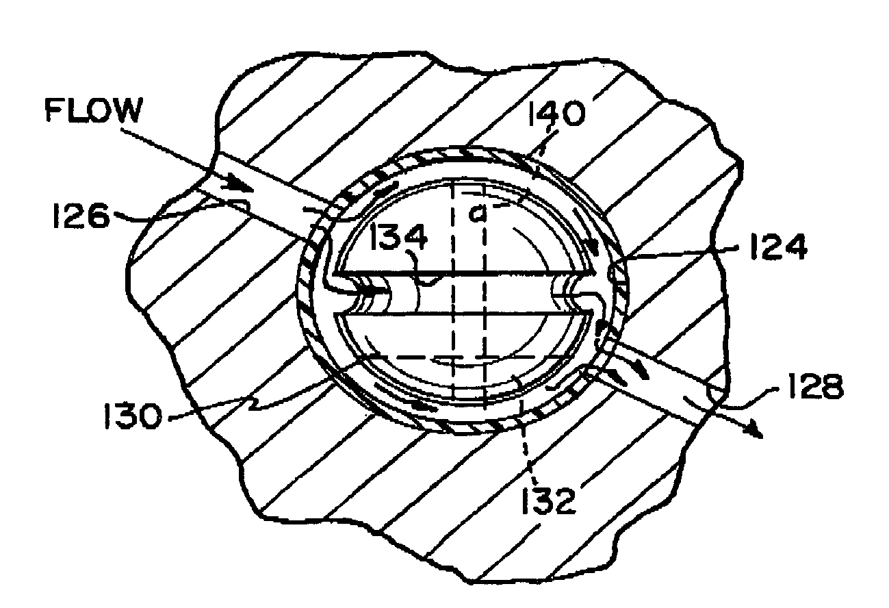
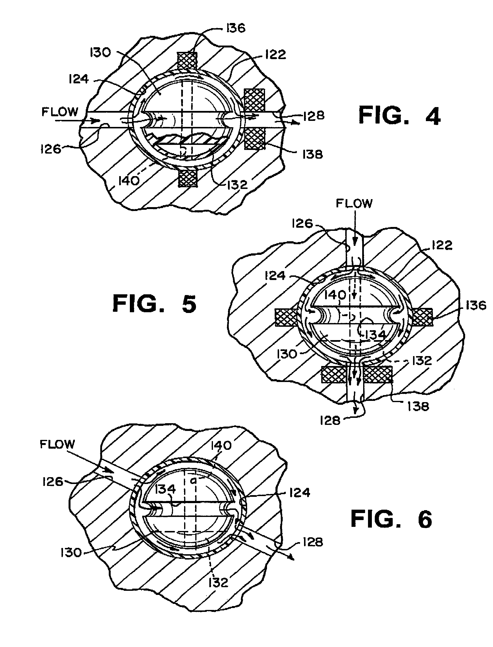
[0020]A subhousing 22 is disposed within housing 20, downstream from one-way valve 18. Subhousing 22 has a spherical inner surface 24 with a predetermined inner diameter. The subhousing 22 has an inlet port 26 for receiving fluid from the first region and an outlet port 28 for directing fluid to the second region. The inlet port 26 and the outlet port 28 are disposed approximately diametrically opposite from each other along essentially the same longitudinal...


PUM


Abstract

An anti-siphon device limits the flow of a fluid from a first region of a patient's body to a second region. The device includes a housing having a spherical inner surface with a predetermined inner diameter. The housing has an inlet port for receiving fluid from the first region and an outlet port for directing fluid to the second region. The inlet port and the outlet port are disposed approximately diametrically opposite from each other. A spherical ball is disposed within the housing. The spherical ball has a ferromagnetic weight disposed off center therein. The spherical ball has an outer diameter that is less than the inner diameter of the housing so that the spherical ball is free to rotate within the housing and the fluid is free to flow between the inner surface of the housing and an outer surface of said spherical ball. The spherical ball has a circumferential recess extending through its center.

Description

BACKGROUND OF THE INVENTION[0001]1. Field of the Invention[0002]The present invention relates to a surgically implantable physiological shunt system and an anti-siphon device. More specifically, the present invention relates to a shunt system including a flow control device for controlling the flow of cerebrospinal fluid out of a brain ventricle.[0003]2. Discussion of the Related Art[0004]Shunt systems for directing body fluid from one region to another are known in the medical field. One application for such a fluid shunt system is in the treatment of hydrocephalus in order to direct cerebrospinal fluid away from the brain and into the venous system or to another region of the body. In this application, a shunt is implanted on the patient's skull, under the scalp, and is coupled to a brain ventricle catheter, which is adapted for insertion into the brain, and to a distal catheter, which is adapted for insertion into the drainage region, such as the peritoneal cavity, the atrium or ...

Claims


Application Information

Patent Timeline
Patent Type & Authority Patents(United States)
IPC IPC(8): A61M5/00F16K31/08A61M27/00
CPCA61M27/006
Inventor CHAN, IAN
Owner INTEGRA LIFESCI SWITZERLAND SARL
Why Eureka
Try Eureka