Accurate positioning brain retractor
A precise positioning and retraction technology, applied in the field of medical devices, can solve the problems of contusion pressure, low accuracy, and elevation of surrounding brain tissue, and achieve the effects of avoiding contusion, convenient operation, and high insertion accuracy
- Summary
- Abstract
- Description
- Claims
- Application Information
AI Technical Summary
Problems solved by technology
Method used
Image
Examples
Embodiment 1
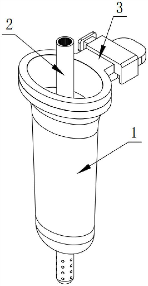
[0046] Such as figure 1 As shown, a precise positioning brain retracting device according to an embodiment of the present invention includes a brain retracting mechanism 1 and a precise positioning guiding mechanism 2 .
[0047] Among them, such as figure 1 As shown, the root-brain retraction mechanism 1 is used to block the soft tissue around the operative field. The brain retraction mechanism 1 includes a retractor and a guide. The retractor is detachably set outside the guide. The length of the retractor, and the guide is used to guide the smooth insertion of the retractor into the soft tissue.
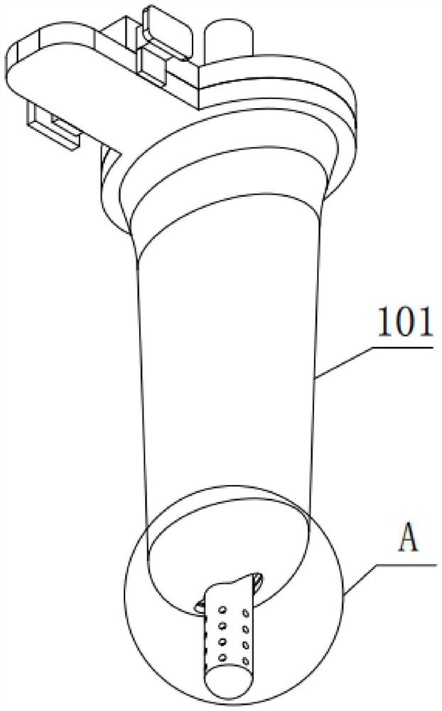
[0048] Among them, such as figure 1 and Figure 10 As shown, the root retractor includes a retraction case 101, the retraction case 101 is a cylindrical structure, and the radial section of the retraction case 101 is elliptical, and the tail end of the retraction case 101 is a flaring end, and the top end of the retracted case 101 is the narrowed end 103.
[0049] Among them, ...
Embodiment 2
[0065] Such as Figure 7 , Figure 9 as well as Figure 10 As shown, the difference between this embodiment and Embodiment 1 is that an annular support seat 107 is fixedly installed on the tail end of the retractable case 101, the annular support seat 107 is elliptical, and the outer ring surface of the annular support seat 107 is A handle 108 is integrally provided.
[0066] Such as Figure 9-Figure 11 As shown, the tail end of the guide case 102 is fixedly installed with an annular fixing seat 104, and the outer ring surface of the annular fixing seat 104 is provided with a locking assembly 3, and the locking assembly 3 is used to connect the annular fixing seat 104 and the annular supporting seat 107 lock each other.
[0067] Among them, such as figure 1 as well as Figure 9-Figure 16 As shown, the locking assembly 3 includes a base 301, a blocking piece 307, a partition 305, a spring seat 304, a cover plate 310, a connecting plate 309, a slider 303, a pressing plate ...
Embodiment 3
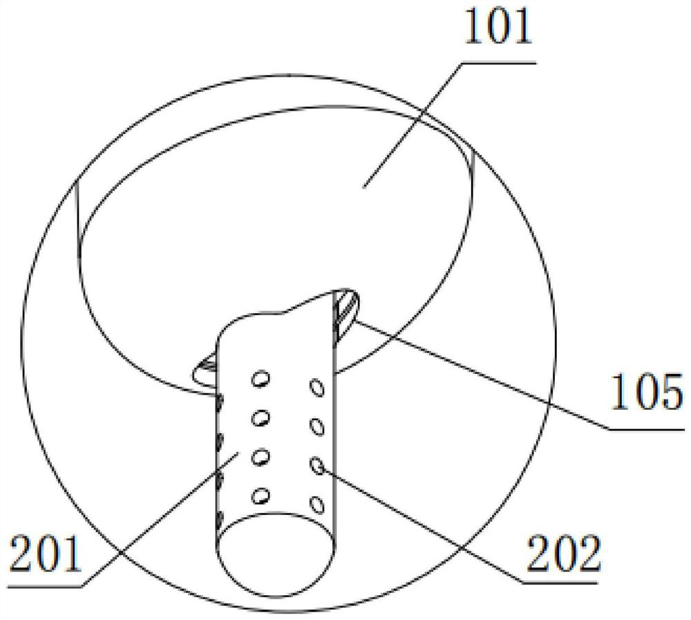
[0071] Such as Figure 6 as well as Figure 8 As shown, the difference between this embodiment and Embodiment 2 is that a transparent silica gel protective layer 203 is fixedly installed inside the hard conduit 201, and a plurality of grooves 204 are evenly opened on the inner wall of the transparent silica gel protective layer 203 to allow liquid to enter The hole 202 is a trumpet-shaped liquid inlet hole, and the small end of the liquid inlet hole 202 is set through the transparent silicone protective layer 203 , and the large end of the liquid inlet hole 202 is located on the outer surface of the hard conduit 201 .
[0072] By adopting the above technical scheme, the set transparent silicone protective layer 203 can not only prevent the navigation from being damaged by the friction of the inner wall of the hard catheter 201, but also prevent the hard catheter 201 from easily falling off from the navigation pen. In addition, the transparent silicone protective layer 203 A n...
PUM
 Abstract
Description
Claims
Application Information
 - R&D
- Intellectual Property
- Life Sciences
- Materials
- Tech Scout
- Unparalleled Data Quality
- Higher Quality Content
- 60% Fewer Hallucinations
Browse by: Latest US Patents, China's latest patents, Technical Efficacy Thesaurus, Application Domain, Technology Topic, Popular Technical Reports.
© 2025 PatSnap. All rights reserved.Legal|Privacy policy|Modern Slavery Act Transparency Statement|Sitemap|About US| Contact US: help@patsnap.com


