Floating power generation system

a power generation system and floating technology, applied in special-purpose vessels, container discharging methods, lighting and heating apparatus, etc., can solve the problems of large-scale natural gas storage dangers, explosions or fires, and achieve the effect of more rapid acquisition of vessels

Active Publication Date: 2006-10-10
SINGLE BUOY MOORINGS INC
View PDF4 Cites 24 Cited by
  • Summary
  • Abstract
  • Description
  • Claims
  • Application Information

AI Technical Summary

Benefits of technology

[0003]In accordance with one embodiment of the invention, applicant provides an offshore system for flowing electricity to a power consumer such as processing equipment that liquefies natural gas so it can be sent by tanker to a distant location, or that regases liquified natural gas that is received from a tanker. The system includes an offshore process vessel that processes gas and that transfers liquified gas to or from a tanker, and also includes a separate generating vessel that contains an electricity generating set. The use of two vessels enables smaller vessels to be used, which enables more rapid acquisition of the vessels. The generating vessel is far (at least 0.2 km) from the process vessel to safeguard personnel on the vessels from an explosion or fire at the process vessel or tanker or at the generating vessel.
[0004]Electricity also can be carried from a generating vessel to an onshore distribution facility. In that case, the generating vessel lies a sufficient distance from shore to avoid on shore damage from any gas fire or explosion on the generating or process vessels, but close enough to enable efficient passage of electricity from the vessel to the onshore distribution facility though a sea floor power cable. The distance is preferably sufficient so the vessels are not clearly visible from shore.

Problems solved by technology

The storage of large quantities of natural gas carries the danger of an explosion or great fire.

Method used


Image

  • Floating power generation system
  • Floating power generation system
  • Floating power generation system

Examples


Embodiment Construction

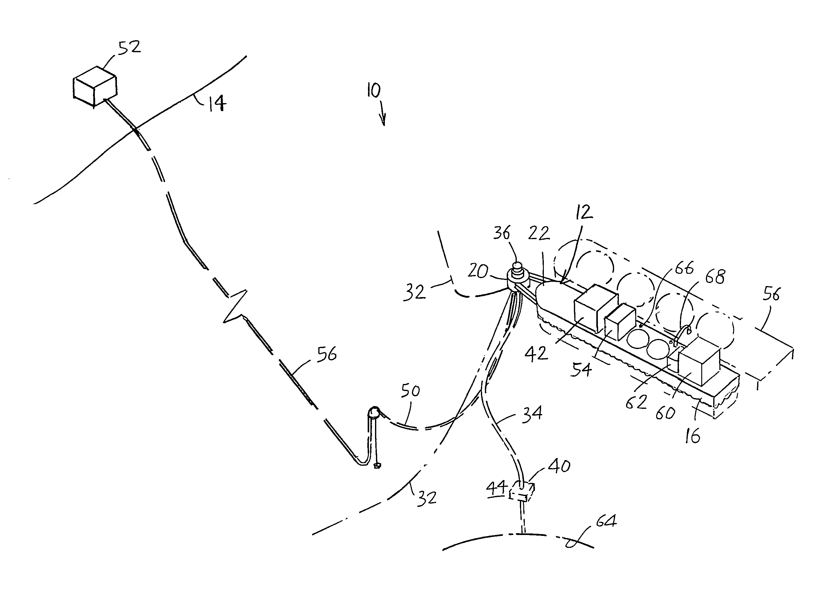
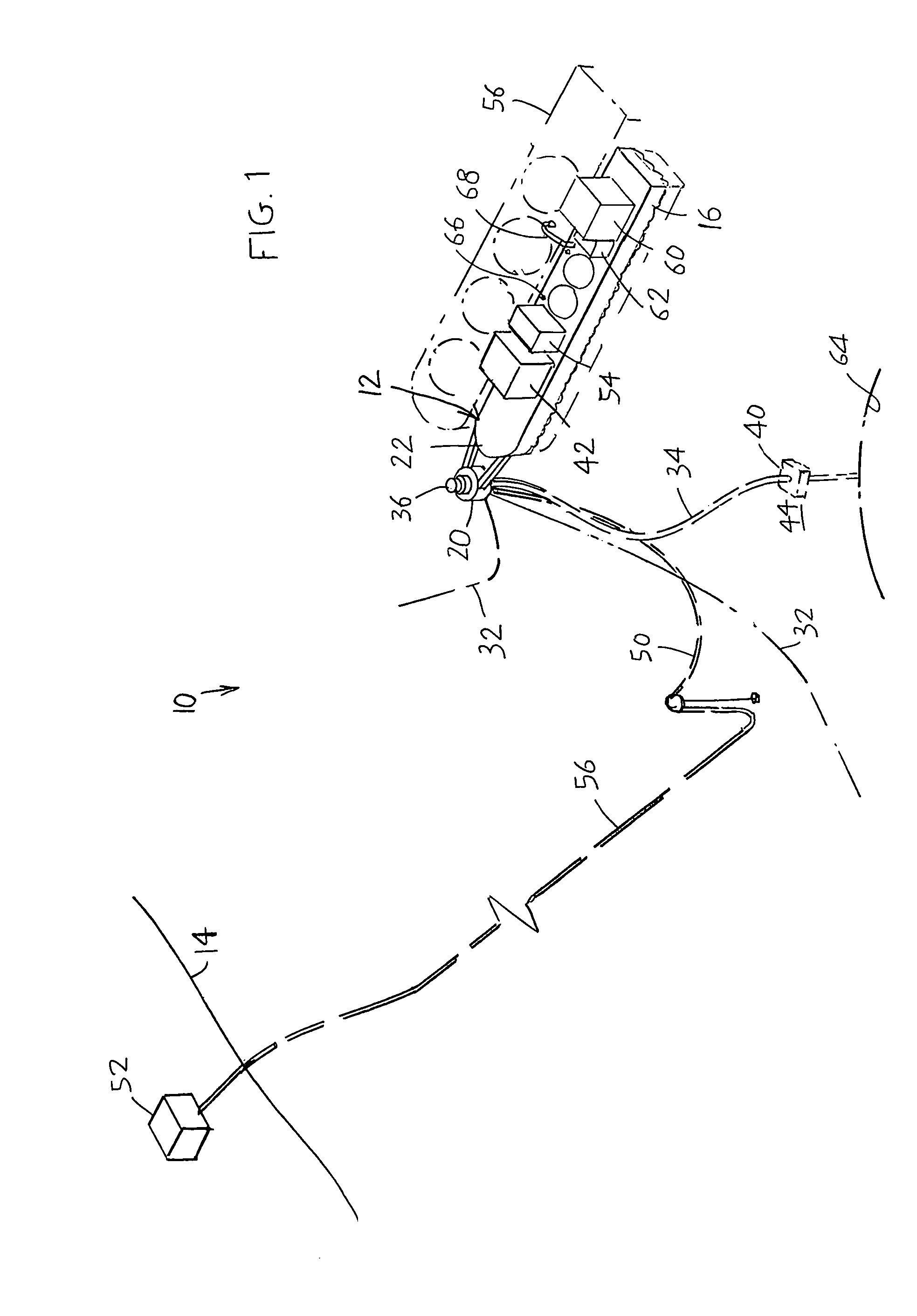
[0009]FIG. 1 illustrates a system 10 for generating large amounts of electricity (at least 30 megawatts), using natural gas as a fuel, which includes a vessel 12 that lies offshore (usually less than about 200 kilometers from shore 14). The vessel, such as a barge, has a hull 16 that supports a turret 20 at its bow end 22. The turret is moored by a mooring system such as catenary lines 32 that extend to the sea floor and along it. Risers 34 extend from a swivel 36 on the turret to a sea floor platform 40. The turret allows the vessel to weathervane, that is, to face in different directions with changing winds and waves, while the catenary lines allow the vessel to drift but only a limited distance, from a location 44 over the sea floor platform. Other mooring systems that can be used instead, including spread mooring.

[0010]The vessel carries an electricity generating unit 42 that uses gas as a fuel to generate electricity. A preferred unit is a turbine-generator set wherein the turb...


PUM


Abstract

A system for using natural gas to safely provide large amounts (at least 30 megawatts) of electricity to consumers. The system includes a floating generating vessel (110) that lies offshore and carries one or more turbine-generator sets (114, 116) that use natural gas as fuel and whose electricity output is delivered though a power line (138) that extends at least partially in the sea to a consumer. One consumer is a process vessel (112) that processes natural gas and that has transfer facilities (68) that transfer liquified gas to or from a tanker (106) that holds over 10,000 tons of liquified gas. Some of the gas is transferred from the process vessel through a conduit (136) in the sea to the generating vessel (110) to provide fuel. Another consumer is an onshore facility (52). The generating and process vessels (110, 112) are widely separated (e.g. at least 0.2 kilometer) to protect personnel in the event of a gas explosion or fire. The separate generating and process vessels enable rapid acquisition of the vessels, which is especially useful to quickly supply large quantities of electricity in newly developed areas.

Description

CROSS-REFERENCE[0001]Applicant claims priority from U.S. provisional applications 60 / 568,811 filed May 6, 2004, 60 / 559,989 filed Apr. 5, 2004, and 60 / 550,133 filed Mar. 4, 2004.BACKGROUND OF THE INVENTION[0002]The storage of large quantities of natural gas carries the danger of an explosion or great fire. Large quantities of natural gas are becoming available by transporting it as liquified gas (by cooling to liquify or hydrate it) by tankers each holding over 10,000 tons of gas, from distant hydrocarbon fields that produce large quantities of natural gas. Such gas (primarily gas with three or four carbon atoms per molecule) may be liquified by a production and processing vessel lying over an offshore hydrocarbon reservoir, and later heated to regas it as its destination. For both liquefaction by cooling and regas by heating, large amounts of electricity are used. It would be desirable if such system for processing gas and generating electricity could be readily acquired. It also wo...

Claims


Application Information

Patent Timeline
Patent Type & Authority Patents(United States)
IPC IPC(8): H05K7/14B60L1/00F25J1/02
CPCF17C7/04F25J1/0022F25J1/02F25J1/0278F25J1/0284F17C2221/033F17C2223/0161F17C2225/0123F17C2227/01F17C2227/0302F17C2260/048F17C2265/05F17C2265/07F17C2270/0105F17C2270/011F17C2270/0126F17C2270/0155F17C2270/0163F25J2240/80
Inventor POLDERVAART, LEENDERTCANN, BRAM VANWILLE, HEINROSEN, LEON D.
Owner SINGLE BUOY MOORINGS INC
Why Eureka
Try Eureka