Brushless DC motor and brushless DC motor controller

a brushless dc motor and motor controller technology, applied in the direction of motor/generator/converter stopper, dynamo-electric converter control, etc., can solve the problems of resonance, increased vibration/noise, and useless normal components, so as to reduce vibration, reduce motor acoustic noise, and reduce the effect of vibration

Active Publication Date: 2006-10-10
DAIKIN IND LTD
View PDF15 Cites 28 Cited by
  • Summary
  • Abstract
  • Description
  • Claims
  • Application Information

AI Technical Summary

Benefits of technology

[0020]It is an object of the present invention to provide a brushless DC motor and brushless DC motor control apparatus which can easily cope with making of motor highly effective and the decreasing of the motor acoustic noise.
[0053]The brushless DC motor control apparatus of the thirteenth aspect according to the present invention determines the motor terminal voltage at the maximum revolution to be equal to or greater than the voltage of the inverter. Therefore, the operating range is enlarged, and operations and effects similar to those of the twelfth aspect are realized.

Problems solved by technology

When the vibration of the frequency corresponding to the order is coincident with a characteristic frequency of a motor, a frame for supporting a motor and the like, the vibration / noise is increased due to the resonance, and may become a subject of discussion.
When an electro-magnetic suction force working between a rotor and a stator during revolution is decomposed into a first component in a tangential direction (circumferential direction) and a second component in a normal direction (radial direction), the tangential component is effectively utilized as a revolution force, but the normal component is useless electro-magnetic suction force which generate only the subject of discussion for vibration / noise.
But, it is required for the demand for reducing vibration / noise of a motor and an entirety of an apparatus in which a motor is incorporated that an electro-magnetic exciting force in the normal direction is reduced which is useless and is a great electro-magnetic force.
But, in many cases, such coping is difficult to be employed by taking disadvantages into consideration that lowering in motor efficiency and the like.
But, when a motor with high efficiency and low noise is desired, and when a noise of a specific order is to be reduced for decreasing of the motor acoustic noise, it is not coped with both the making of motor highly effective and decreasing of the motor acoustic noise, for every angle within an extent where the improvement in efficiency is realized.
Such determination cannot easily be realized for even a person having an ordinary skill in the art.
Tokukai 2002-44888, it is further difficult that both the making of motor highly effective and the decreasing of the motor acoustic noise are coped with.
Tokukaihei 11-98731, it is not possible that both the making of motor highly effective and the decreasing of the motor acoustic noise are coped with.
Tokukal 2000-217287, it is not possible that both the making of motor highly effective and the decreasing of the motor acoustic noise are coped with.
Therefore, it is not possible that both the making of motor highly effective and the decreasing of the motor acoustic noise are coped with.

Method used


Image

  • Brushless DC motor and brushless DC motor controller
  • Brushless DC motor and brushless DC motor controller
  • Brushless DC motor and brushless DC motor controller

Examples


Embodiment Construction

[0070]Hereinafter, referring to the attached drawings, we explain a brushless DC motor and brushless DC motor control apparatus of embodiments according to the present invention, in detail.

[0071]First, it is explained how decreasing in noise and an angle θ0 are determined.

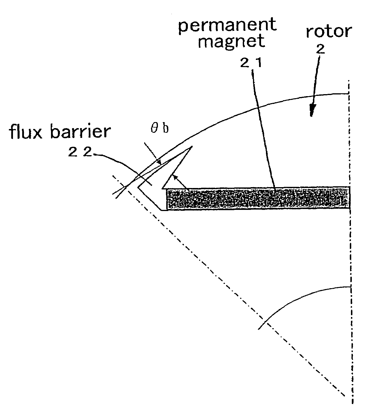
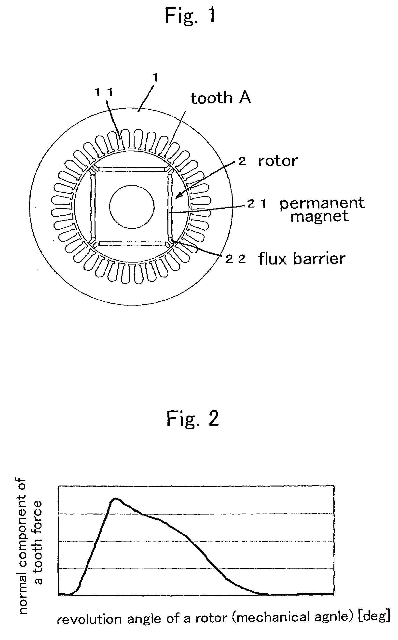
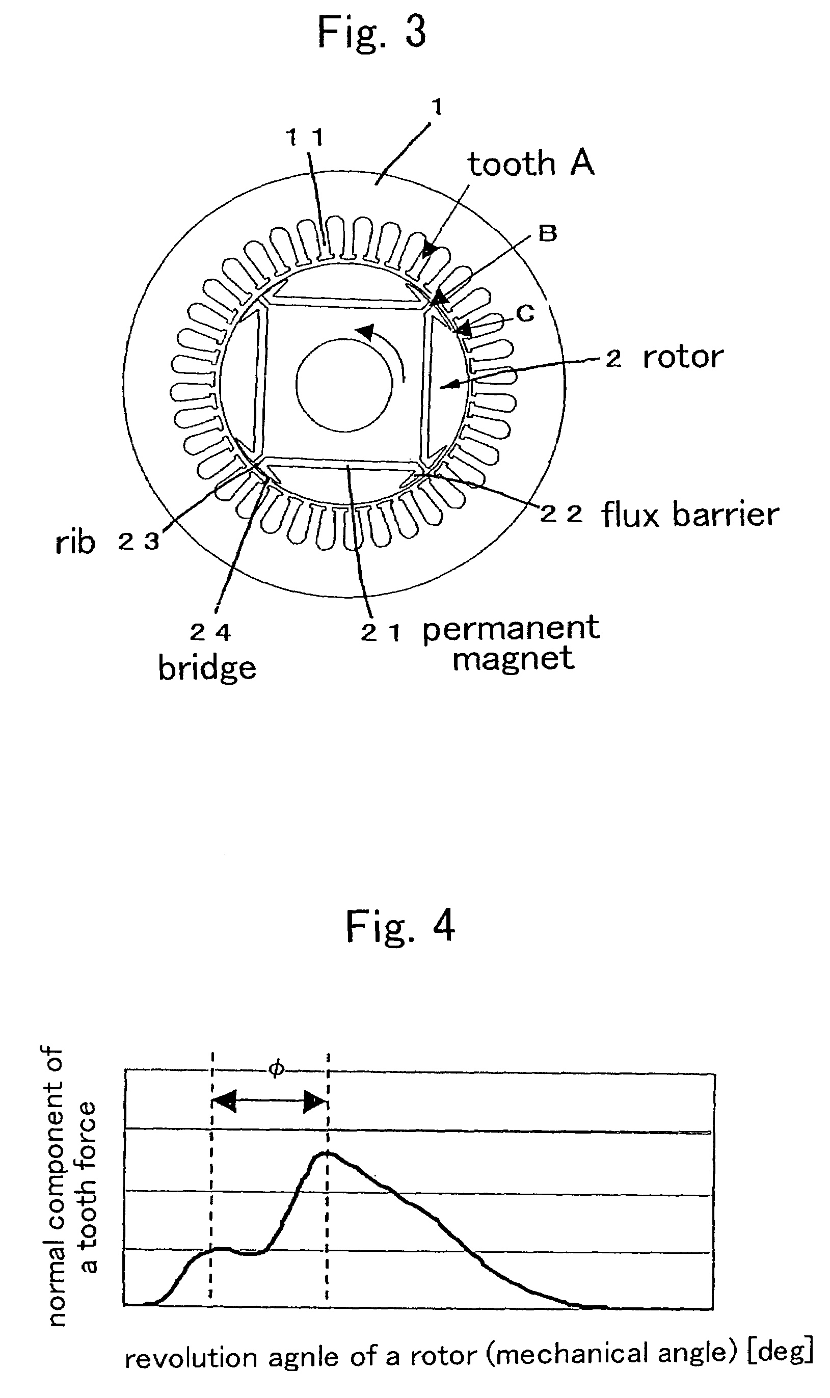
[0072]FIG. 1 is a vertical cross sectional view illustrating an arrangement of a conventional brushless DC motor. The brushless DC motor comprises a stator 1 which is formed a number of teeth 11, and a rotor 2 which houses permanent magnets 21 in its interior and has barriers for preventing magnetic flux short circuit, each of the barriers extending from an edge section of the permanent magnet 21 towards the outer surface of the rotor.

[0073]FIG. 2 is a diagram illustrating an exciting force (normal component) applied to a tooth A during operation of a brushless DC motor having a rotor which has a width of a barrier 22 which is close to the thickness of the permanent magnet 21.

[0074]As is understood from FIG. 2, the...


PUM


Abstract

A brushless DC motor has a stator and a rotor. An angle θ0 between an edge section of the flux barrier on a magnetic pole center side and an edge section on a side for coming in contact with the rib of adjacent flux barrier, with respect to the rotor center, is determined to be equal to or greater than an angle satisfying a following relationshipθ0=180°*m / (Pn*f / f0) (provided 2θ0−θr<90°)wherein, a frequency of vibration which is to be reduced is represented with f, a pole pair number is represented with Pn, an electrical frequency is represented with f0=Pn*N, a motor revolution is represented with N, m=1, 3, 5, . . . , an angle of the rib with respect to the rotor center is represented with θr, therefore making of motor highly effective and decreasing of the motor acoustic noise are coped with.

Description

CROSS-REFERENCE TO RELATED APPLICATIONS[0001]This nonprovisional application claims priority under 35 U.S.C. § 119(a) to Japanese Patent Application No. 2002-345980, filed in Japan on Nov. 28, 2002, the entire content of which is hereby incorporated by reference.TECHNICAL FIELD[0002]The present invention relates to a brushless DC motor and brushless DC motor control apparatus. More particularly, the present invention relates to a novel brushless DC motor and brushless DC motor control apparatus which can cope with both making of motor highly effective and decreasing of the motor acoustic noise.RELATED ART[0003]From the past, it was proposed that a dimension in peripheral direction of a flux barrier is determined to be equal to or greater than a thickness of a magnet so as to improve efficiency (refer to Japanese Patent Laid-open Gazette No. Tokukai 2002-44888).[0004]It is also proposed that decreasing of the motor acoustic noise is intended to be realized by an angle of a flux barri...

Claims


Application Information

Patent Timeline
Patent Type & Authority Patents(United States)
IPC IPC(8): H02P1/18H02K29/00H02K1/27H02K21/14H02K29/03
CPCH02K1/276H02K29/03H02K21/14H02P7/025
Inventor NISHIJIMA, KIYOTAKA
Owner DAIKIN IND LTD
Why Eureka
Try Eureka