Test probe alignment apparatus

a technology of alignment apparatus and test probe, which is applied in the direction of measurement leads/probes, semiconductor/solid-state device testing/measurement, instruments, etc., can solve the problems of inertia of the entire workpiece positioning stage, affecting positioning speed and accuracy, and stage can also be a source of positioning error, so as to facilitate the engagement of test probes, improve the speed and accuracy of chuck movements, and inhibit the vibration in and inertia of the workpi

Inactive Publication Date: 2006-10-10
ELECTRO SCI IND INC
View PDF17 Cites 53 Cited by
  • Summary
  • Abstract
  • Description
  • Claims
  • Application Information

AI Technical Summary

Benefits of technology

[0010]An alignment apparatus is adapted for aligning a set of test probes or other tools with a set of contact areas on a substrate, such as a printed circuit board panel or finished silicon wafer. The substrate is supported on a chuck of a workpiece positioning stage for linear movement in an X-Y plane. The alignment apparatus also facilitates engagement of the test probes with the contact areas

Problems solved by technology

Furthermore, in systems having a θ stage supported on the X-Y stage, the mass of the θ stage adds to the inertia of the entire workpiece positioning stage.
The added inertia slows movement in the X and Y directions and raises the center of mass of the workpiece positioning stage, thereby affecting positioning speed and accuracy.
The θ stage can also be a source of positioning error due to vibration and backlash that are induced in the θ stage mechanism each time the X-Y stage is actuated.
Overall, the coupling of the θ stage with the workpiece positioning stage in conventional test probe alig

Method used


Image

  • Test probe alignment apparatus
  • Test probe alignment apparatus
  • Test probe alignment apparatus

Examples


Embodiment Construction

[0026]Throughout the specification, reference to “one embodiment,” or “an embodiment,” or “some embodiments” means that a particular described feature, structure, or characteristic is included in at least one embodiment. Thus, appearances of the phrases “in one embodiment” or “in an embodiment” or “in some embodiments” in various places throughout the specification are not necessarily all referring to the same embodiment or embodiments.

[0027]Furthermore, the described features, structures, or characteristics may be combined in any suitable manner in one or more embodiments. Those skilled in the art will recognize that the invention can be practiced without one or more of the specific details, or with other methods, components, materials, etc. In other instances, well-known structures, materials, or operations are not shown or not described in detail to avoid obscuring aspects of the embodiments.

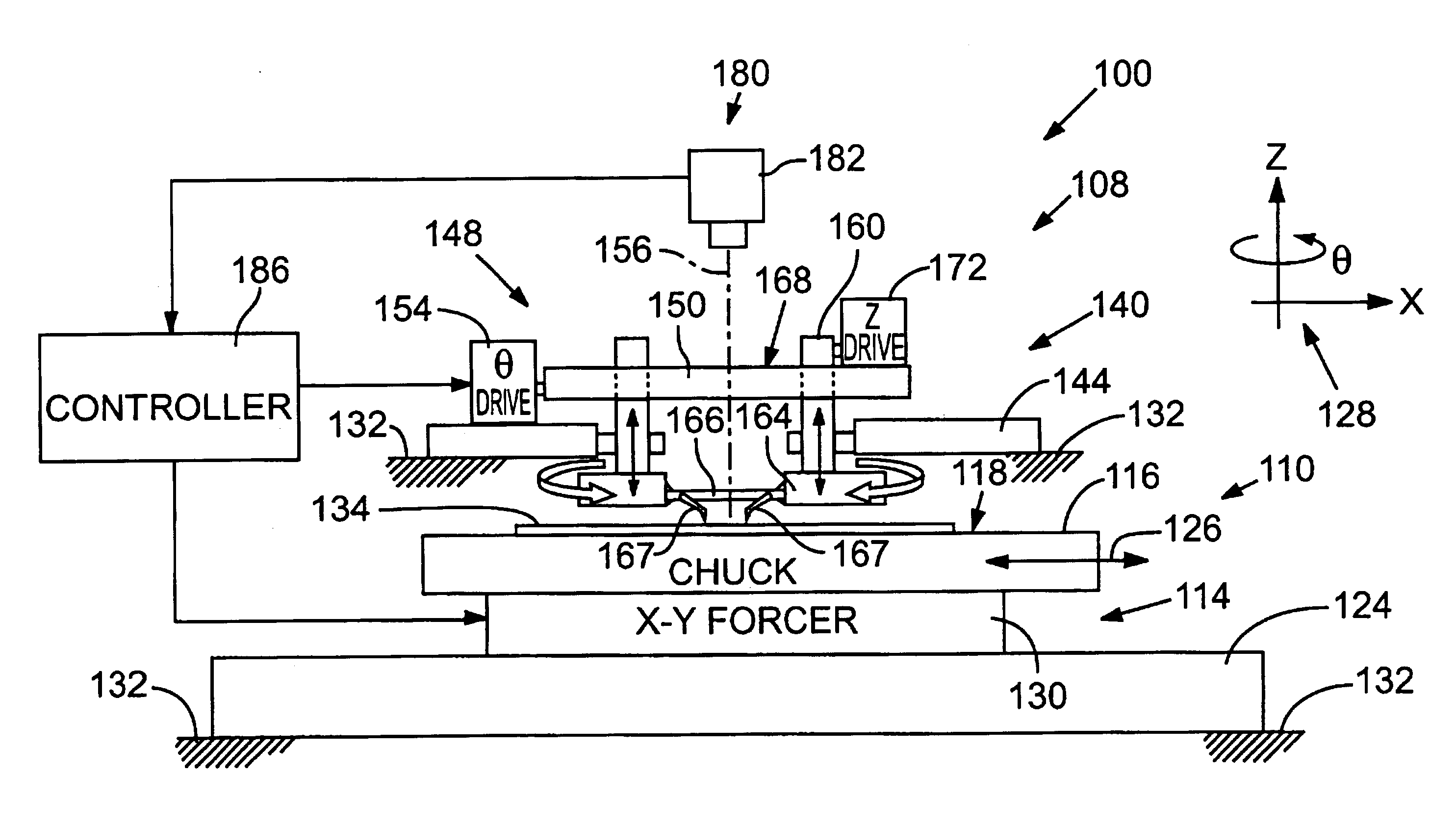
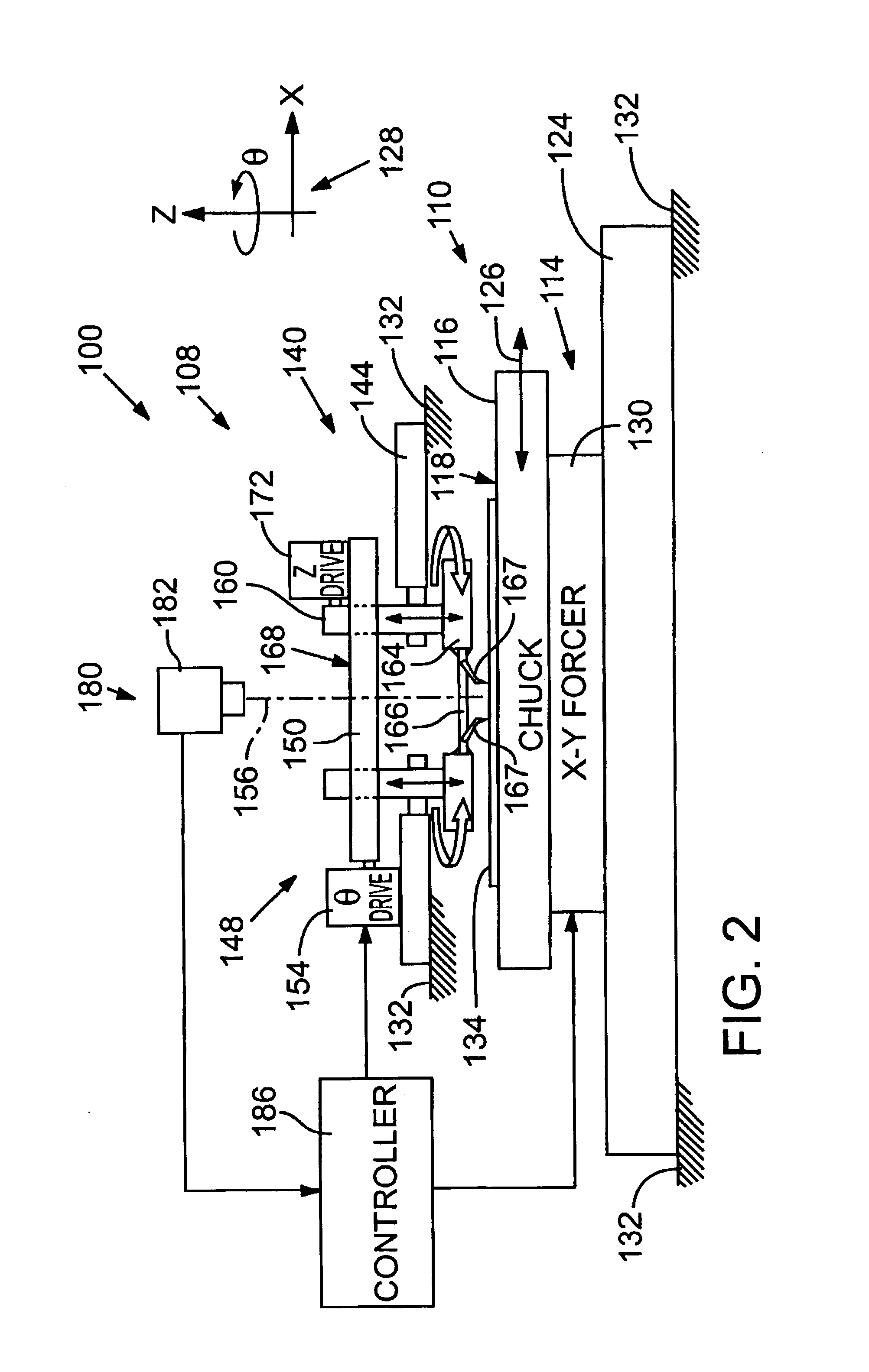
[0028]FIG. 2 is a schematic front elevation of a test probing system 100 including a test...


PUM


Abstract

A test probe alignment apparatus includes a rotatable θ stage that is decoupled from a workpiece positioning stage so that the workpiece positioning stage can move a workpiece in an X-Y plane without moving the θ stage, thereby inhibiting vibration in and inertia of the workpiece positioning stage, and improving the speed and accuracy of workpiece movements. The θ stage is driven for rotation about an axis substantially perpendicular to the X-Y plane. The rotatable stage supports a carriage adapted for holding a probe card. The carriage rotates in concert with the θ stage to thereby align the probe card relative to the workpiece. A Z-stage is operatively engaged with the carriage for moving the carriage along the axis of rotation relative to the workpiece. A computer processor performs coordinate transformations on preprogrammed movement vectors, to adjust for angular misalignment of the workpiece as measured by a position sensor.

Description

RELATED APPLICATIONS[0001]This application claims the benefit under 35 U.S.C. § 119(e) of U.S. Provisional Patent Application No. 60 / 366,912, filed Mar. 22, 2002, which is incorporated herein by reference.TECHNICAL FIELD[0002]This application relates to alignment apparatuses for use in testing, drilling, and trimming of printed circuit boards and integrated circuit substrates and, in particular, to an improved alignment apparatus that isolates a rotational positioning mechanism (θ stage) of the apparatus from the effects of a translating workpiece positioning mechanism (X-Y stage), and vice versa.BACKGROUND OF THE INVENTION[0003]The manufacture of electronic circuits such as printed circuit boards and integrated circuits typically involves inspection and testing of each circuit in an array of circuit patterns formed on a substrate. Calibration of circuits may include probing and measurement of electrical characteristics of circuit components during a laser trimming operation that ad...

Claims


Application Information

Patent Timeline
IPC IPC(8): G01R31/02G01R1/06G01R31/28H01L21/66
CPCG01R31/2887G01R31/2831G01R1/073
Inventor KIM, KYUNG Y.
Owner ELECTRO SCI IND INC
Why Eureka
Try Eureka