Near field to far field DF antenna array calibration technique

a df antenna array and calibration technique technology, applied in the direction of antenna radiation diagrams, instruments, antennas, etc., can solve the problems of inability to test large antennas in the far field, complex processing solutions for most compact antenna range processing solutions, and serious limitations on the maximum size of antennas that can be measured

Inactive Publication Date: 2006-10-10
OL SECURITY LIABILITY CO
View PDF5 Cites 112 Cited by
  • Summary
  • Abstract
  • Description
  • Claims
  • Application Information

AI Technical Summary

Benefits of technology

[0026]In accordance with the teaching of the preferred embodiment of the invention the calibration weighting factor calculations for each test point on the hemisphere are made using a least mean square calculating algorithm, such as a gradient based convergence algorithm. For each test point the calculation of weighting factors (amplitude—and phase if necessary) uses the weighting factors calculated for a number of surrounding test points to thereby define the best emulated, in phase, constant amplitude planar wave front over the surface of the turntable. This is a complex weighting and summing process that effe

Problems solved by technology

As is known in the prior art, antennas that transmit or receive signals directionally must be calibrated when they are mounted on platforms of any type because the platforms create measurement errors due to mechanical distortions in the antennas and spurious reflections, such as multi-path reflections, from portions of the platform on which the antenna is mounted.
In view of various problems, including those described in the previous paragraph, it is impractical to test large antennas in the far field.
Unfortunately, when applied to the DF array calibration problems most compact antenna range processing solutions are much more complex than required for DF array manifold generation.
Each has particular advantages for certain applications, but all have serious limitations for the maximum size of antenna that can be measured.
Probe scanning arrangements of this type are complex because the probe must be accurately moved in two directions (X,Y) to cover the entire measurement (scan) plane.
A planar scanner is extremely expensive to fabricate as it gets larger because of the high mechanical tolerances that must be maintained to obtain high quality measurement results.
Again, as the antenna size grows, the method becomes very expensive and is not practical for extremely large antennas.
Also, the computation of the far field is a little more difficult because the data samples a

Method used


Image

  • Near field to far field DF antenna array calibration technique
  • Near field to far field DF antenna array calibration technique
  • Near field to far field DF antenna array calibration technique

Examples


Embodiment Construction

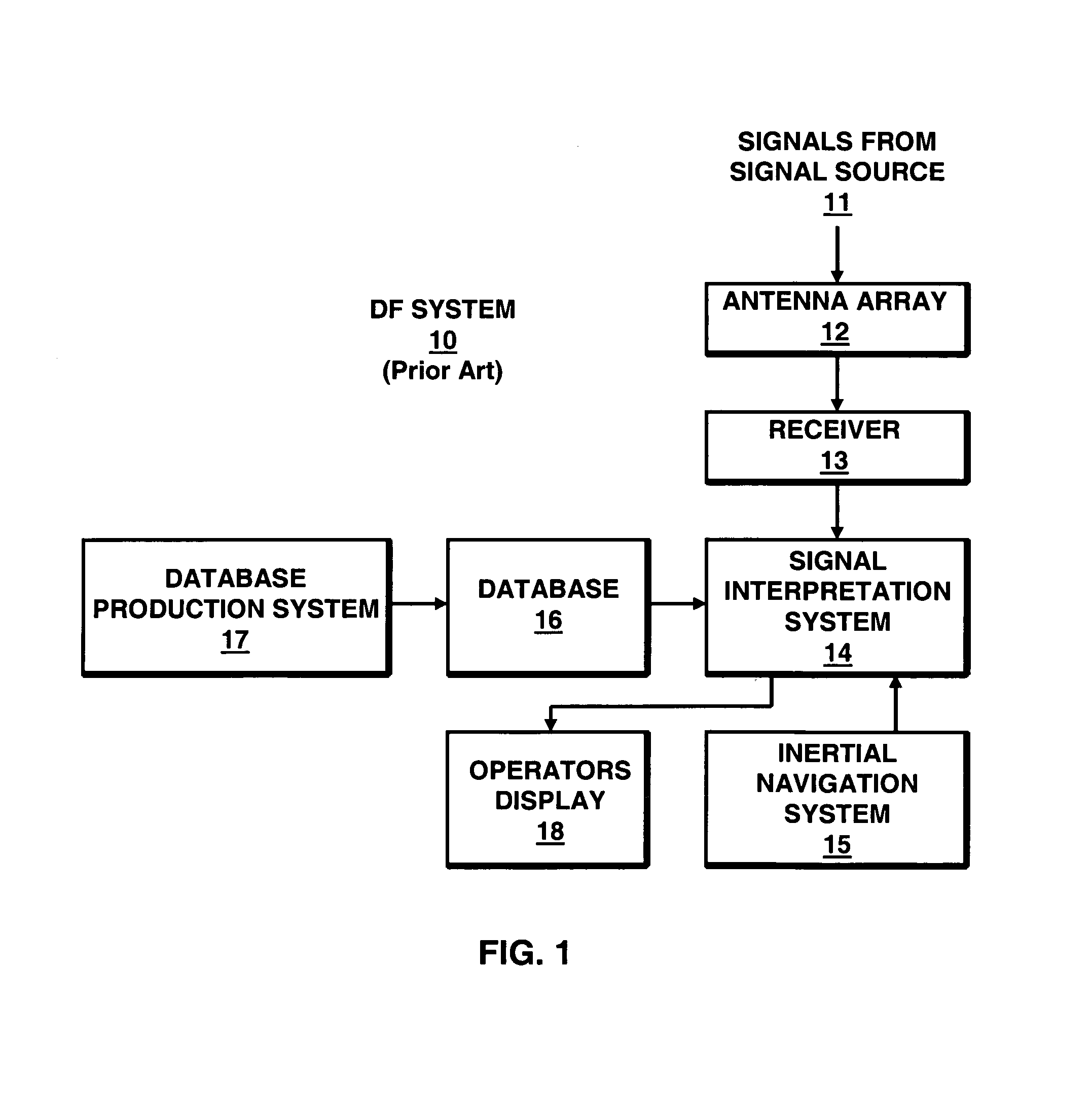
[0042]In FIG. 1 is shown a block diagram of a prior art direction finding (DF) system used for receiving and accurately interpreting radio frequency (RF) signals from a remote signal source 11. In actual operation signals received by DF antenna array 12 from a remote signal source 11 may be any one of a number of types of signals. For example, DF system 10 may be used in a communication intercept application in which the received signals are from, for example, aircraft or ground emitter produced RF communication transmissions in the VHF through L bands of the electromagnetic frequency spectrum. If DF system 10 is on an aircraft, an independent inertial navigational system 15 is also required in order to perform an accurate determination of the location of the aircraft so the signals from source 11 can be accurately determined.

[0043]DF system 10 includes a receiver 13 and a signal interception and DF system 14. Signal interception and DF system 14 uses a database 16 which is stored b...


PUM


Abstract

A technique is disclosed for calculating the phase and amplitude weighting factors for use with a specific compact antenna range that synthesize an in phase, constant amplitude planar wave front that appears to have been transmitted from the far field. The weighting factors are used to weight RF signals after they are received by a full size or scaled radio direction finding array mounted on a platform during testing of the antenna array on the compact antenna range. The weighted received signals accurately replicate the antenna array response in the far field, including electromagnetic glint caused by the platform on which the antennas are mounted, and are stored in complex voltage form as a calibration table for the array.

Description

CROSS REFERENCE TO RELATED APPLICATION[0001]This utility patent application relates to U.S. provisional patent application No. 60 / 380,505, entitled “Planar Wave Synthesis of DF Array Calibration Manifolds From Near-Field Fresnel Zone Measurements”, and filed May 14, 2002.FIELD OF THE INVENTION[0002]This invention relates generally to compact antenna range measurements and a technique for transforming near field antenna measurements into accurate far field patterns that can be used for far field direction finding array calibration manifolds and other antenna array outputs.BACKGROUND OF THE INVENTION[0003]As is known in the prior art, antennas that transmit or receive signals directionally must be calibrated when they are mounted on platforms of any type because the platforms create measurement errors due to mechanical distortions in the antennas and spurious reflections, such as multi-path reflections, from portions of the platform on which the antenna is mounted.[0004]In the prior a...

Claims


Application Information

Patent Timeline
IPC IPC(8): G01S7/40H01Q3/26
CPCG01R29/10G01S3/023H01Q3/04H01Q7/00H01Q19/175
Inventor STRUCKMAN, KEITH A.
Owner OL SECURITY LIABILITY CO
Why Eureka
Try Eureka