Plate-based microelectromechanical switch having a three-fold relative arrangement of contact structures and support arms

a microelectromechanical switch and contact structure technology, applied in the field of microelectromechanical devices, can solve the problems of increasing the complexity of the circuit, the switch may not open reliably (or at all), and the actuation voltage is relatively high, so as to reduce the likelihood of the switch malfunctioning, improve the opening reliability of the switch, and prevent the moveable electrode

Inactive Publication Date: 2006-10-10
TERAVICTA TECH
View PDF8 Cites 27 Cited by
  • Summary
  • Abstract
  • Description
  • Claims
  • Application Information

AI Technical Summary

Benefits of technology

[0017]There may be several advantages to fabricating a plate-based MEMS switch with the configurations described above. In particular, a more stable plate-based MEMS switch may be fabricated as compared to conventional designs due to inclusion of a multiple of three support arms uniformly spaced about the moveable electrode and a plurality of contact structures interposed between the moveable electrode and fixed electrode. Such stability may aid in preventing the moveable electrode from collapsing or bending onto the underlying gate electrode, reducing the likelihood of the switch of malfunctioning. As a result, the stability of the plate-based MEMS switch described herein may allow an electrode to be moved uniformly in a vertical direction. Preventing the moveable electrode from collapsing or bending onto the underlying gate electrode may be particularly evident in embodiments in which the arrangement of contact structures are congruent relative to different regions of the moveable electrode.
[0018]In some configurations, the MEMS switch described herein may additionally offer manners in which to improve the opening reliability of the switch. In particular, electrically inactive contact structures within the MEMS switch described herein may include materials which are less susceptible to stiction. In addition, contact structures may be arranged congruent relative to different regions of the moveable electrode causing a slight variation of contact forces on the structures when an actuation voltage is applied. A slight variation of contact forces may allow contact structures to be released at different times, reducing the energy needed to release all contact structures and thereby increasing the opening reliability of the switch.

Problems solved by technology

Consequently, actuating a switch at a relatively low voltage tends to make the switch harder to open, resulting in a switch which may not open reliably (or at all).
Such relatively high actuation voltages, however, often require voltage translation circuits when used with transistor switches, increasing the complexity of the circuit.
In addition, relatively high actuation voltages increase the force attracting the electrodes of a MEMS switch.
In some cases, the actuation voltages may be high enough to cause the electrodes to contact, causing the device to malfunction.
Such an adaptation of support structures, however, may cause plate-based MEMS switches to be more susceptible to having electrodes collapse onto each other, particularly at high actuation voltages.
In addition, high actuation voltages may cause the plate itself to bend such that a portion of the plate contacts the underlying gate electrode, particularly if the plate is not evenly supported by the structures.
Consequently, the tolerance of actuation voltages for plate-based MEMS switches are often small or cannot be effectively optimized to allow the switches to be reliably opened and closed while simultaneously preventing the actuation electrodes of the switches from contacting one another.

Method used


Image

  • Plate-based microelectromechanical switch having a three-fold relative arrangement of contact structures and support arms
  • Plate-based microelectromechanical switch having a three-fold relative arrangement of contact structures and support arms
  • Plate-based microelectromechanical switch having a three-fold relative arrangement of contact structures and support arms

Examples


Embodiment Construction

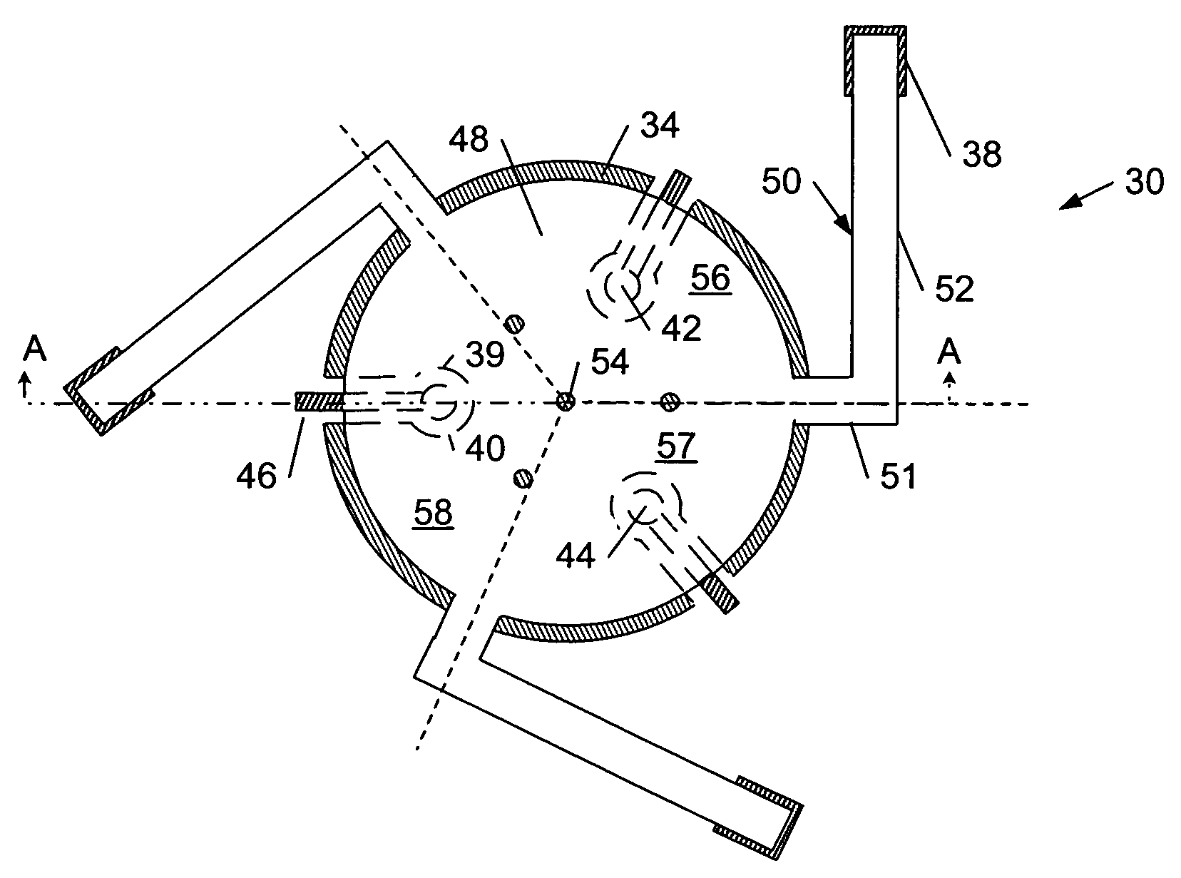
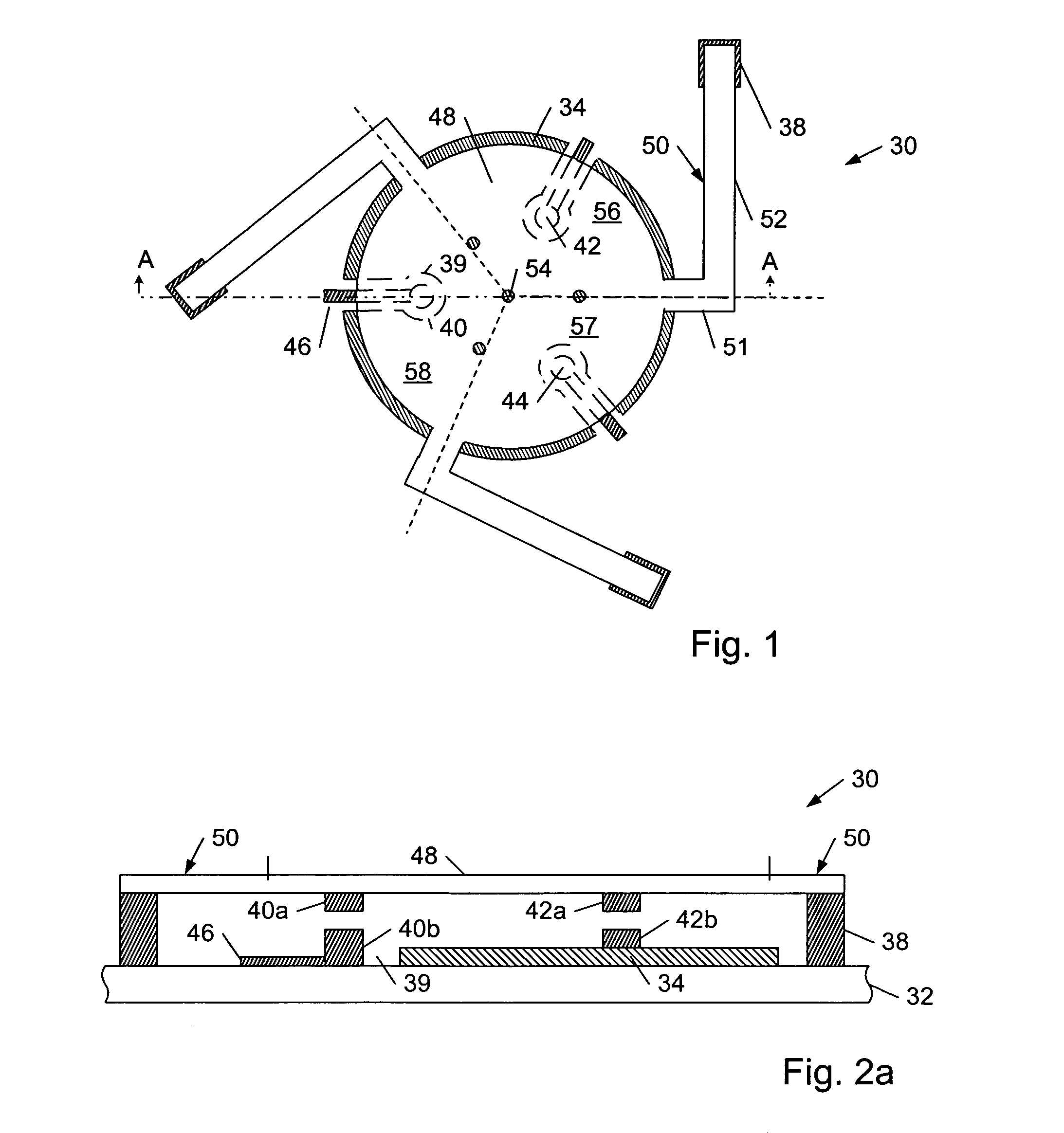
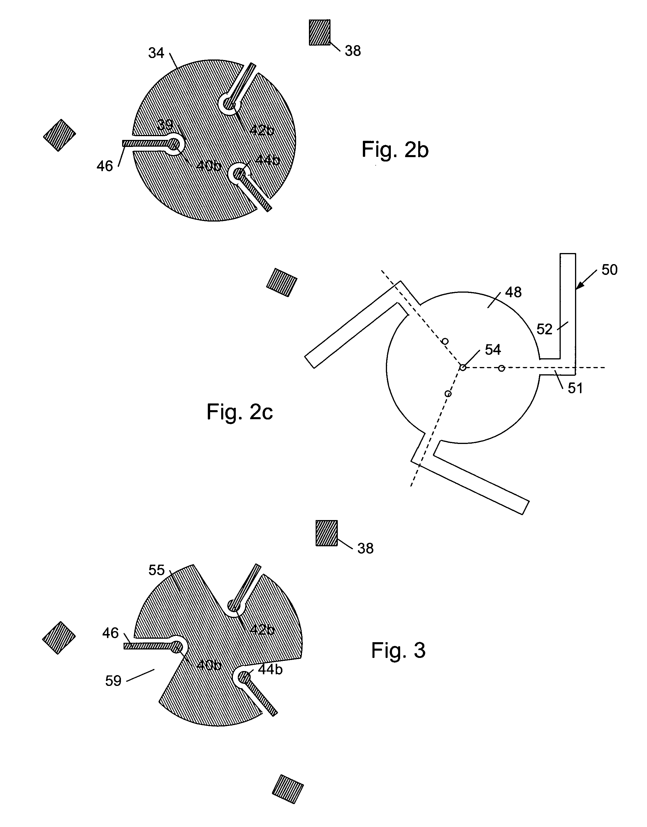
[0046]Turning to the drawings, exemplary configurations of plate-based microelectromechanical switches are shown. In particular, FIGS. 1 and 2a–2c illustrate MEMS switch 30 with moveable electrode 48 arranged above fixed electrode 34. As noted above, the terms “MEMS switch” and “micro-electromechanical switch” are used interchangeably herein, although the acronym “MEMS” does not correspond exactly. FIG. 1 is a plan view of MEMS switch 30 and FIG. 2a is a cross-sectional view of MEMS switch 30 taken along line AA of FIG. 1. FIG. 2b illustrates a plan view of the lower components of MEMS switch 30 (i.e., fixed electrode 34, support via 38, contact sub-structures 40b, 42b and 44b, and signal wires 46) and FIG. 2c illustrates a plan view of the upper components of MEMS switch 30 (i.e., moveable electrode 48 and support arms 50). FIGS. 1 and 2a–2c are discussed concurrently in reference to the configuration of MEMS switch 30. It is noted that the MEMS switch described herein is not restr...


PUM


Abstract

A microelectromechanical system (MEMS) switch is provided which includes a multiple of three support arms extending from the periphery of a moveable electrode. In addition, MEMS switch includes a plurality of contact structures having portions extending into a space between a fixed electrode and the moveable electrode. In some cases, the relative arrangement of the support arms and the contact structures are congruent among three regions of the MEMS switch which collectively comprise the entirety of the fixed electrode and the entirety of the moveable electrode. In other embodiments, the contact structures may not be arranged congruently within the MEMS switch.

Description

BACKGROUND OF THE INVENTION[0001]1. Field of the Invention[0002]This invention relates to microelectromechanical devices, and more particularly, to the arrangement and number of contact structures and support beams within a plate-based microelectromechanical device.[0003]2. Description of the Related Art[0004]The following descriptions and examples are not admitted to be prior art by virtue of their inclusion within this section.[0005]Microelectromechanical devices, or devices made using microelectromechanical systems (MEMS) technology, are of interest in part because of their potential for allowing integration of high-quality devices with circuits formed using integrated circuit (IC) technology. As compared to transistor switches formed with conventional IC technology, for example, microelectromechanical contact switches may exhibit lower losses and a higher ratio of off-impedance to on-impedance. MEMS switch designs generally use an actuation voltage to close the switch, and typic...

Claims


Application Information

Patent Timeline
Patent Type & Authority Patents(United States)
IPC IPC(8): G02B26/00
CPCH01H59/0009
Inventor NELSON, RICHARD D.FLYNN, WILLIAM G.GOINS, DAVID A.
Owner TERAVICTA TECH
Why Eureka
Try Eureka