Perpendicular magnetic head having modified shaping layer for direct plating of magnetic pole piece

a technology shaping layer, which is applied in the field of perpendicular magnetic head with electroplated pole tip, can solve the problems of increasing the probability of damage to the pole tip during subsequent fabrication steps, creating unwanted voids within the material of the pole tip, and affecting the quality of the material

Inactive Publication Date: 2006-10-10
WESTERN DIGITAL TECH INC
View PDF7 Cites 6 Cited by
  • Summary
  • Abstract
  • Description
  • Claims
  • Application Information

AI Technical Summary

Benefits of technology

[0013]It is a further advantage of the hard disk drive of the present invention that it includes a magnetic head of the present invention wherein the magnetic pole tip is electroplated within the magnetic head without having an electroplating seed layer deposited beneath the pole tip.
[0014]It is yet another advantage of the hard disk drive of the present invention that it includes a magnetic head of the present invention wherein no electroplating seed layer of the pole tip is present at the ABS surface of the head.
[0015]It is yet a further advantage of the hard disk drive of the present invention that it includes a magnetic head of the present invention wherein a layer of non-magnetic material is disposed between the ABS surface and the relatively large shaping layer of the second magnetic pole of the magnetic head.
[0016]It is an advantage of the fabrication process of the magnetic head of the present invention that the pole tip is fabricated subsequent to the fabrication of a shaping layer of a second magnetic pole, such that the likelihood of damage to the pole tip is reduced.
[0017]It is another advantage of the method for fabricating a magnetic head of the present invention that the pole tip is fabricated by an electroplating process directly upon a layer of non-magnetic, electrically conductive material.
[0018]It is a further advantage of the method for fabricating a magnetic head of the present invention that the pole tip is fabricated in an electroplating process without the use of an electroplating seed layer beneath the pole tip.

Problems solved by technology

Such submicron sized magnetic pole tips are quite fragile, and are easily malformed, and / or damaged during the magnetic head fabrication process.
Particularly, some fabrication processes utilize a sputter deposition technique for fabricating the pole tips; however, this technique can lead to the creation of unwanted voids within the pole tip material.
Additionally, where the pole tip is fabricated earlier in the magnetic head fabrication process, rather than later, an increased occurrence of damage to the pole tips during subsequent fabrication steps occurs.

Method used


Image

  • Perpendicular magnetic head having modified shaping layer for direct plating of magnetic pole piece
  • Perpendicular magnetic head having modified shaping layer for direct plating of magnetic pole piece
  • Perpendicular magnetic head having modified shaping layer for direct plating of magnetic pole piece

Examples


Embodiment Construction

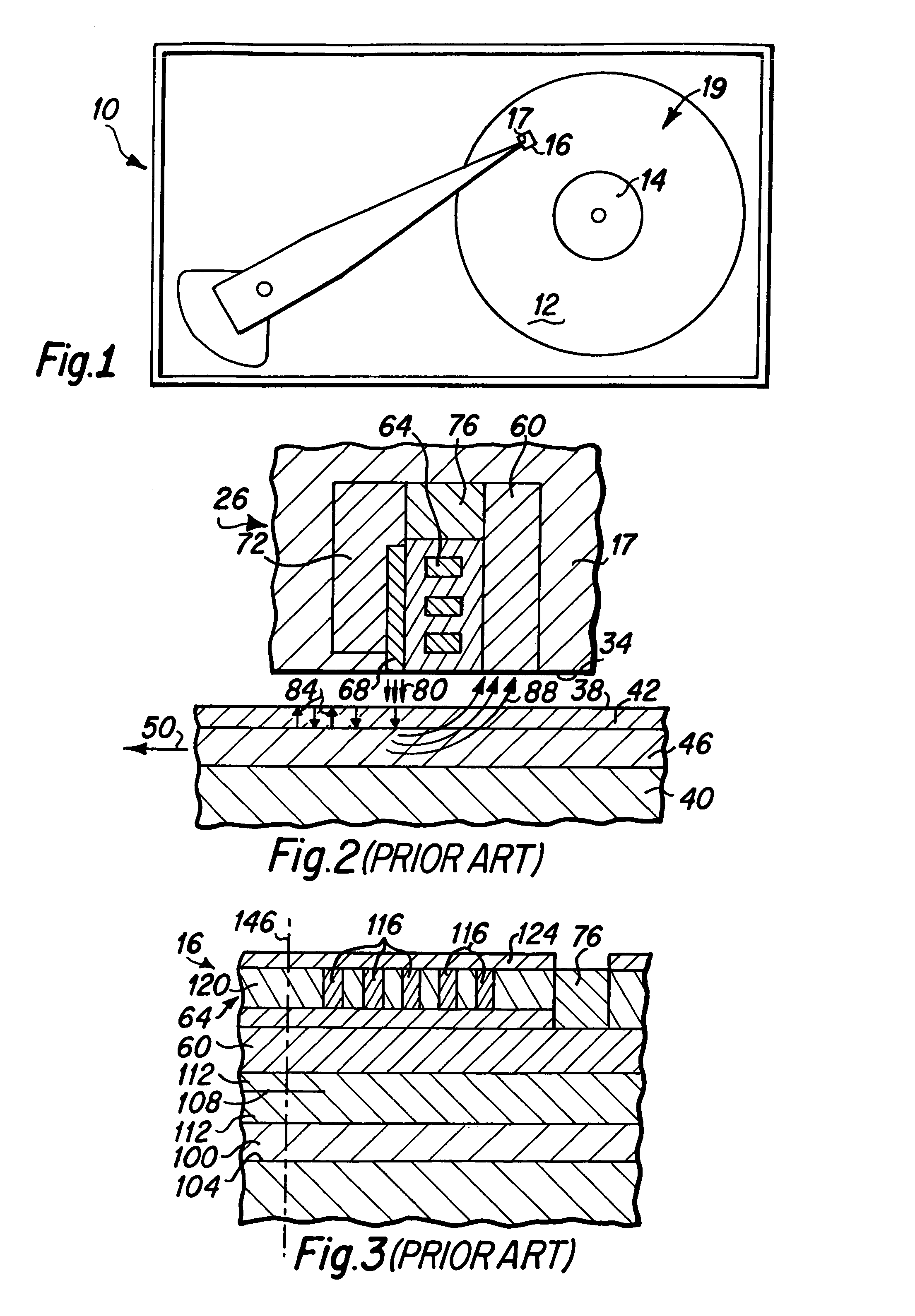
[0025]The magnetic heads of the present invention are utilized to read and write data to magnetic media, such as hard disks in a hard disk drive. A simplified top plan view of a hard disk drive 10 is presented in FIG. 1, wherein at least one magnetic media hard disk 12 is rotatably mounted upon a spindle 14. A magnetic head 16 of the present invention is formed upon a slider 17 that is mounted upon an actuator arm 18 to fly above the surface 19 of each rotating hard disk 12, as is well known to those skilled in the art.

[0026]FIG. 2 is a side cross-sectional diagram of a typical prior art perpendicular write head portion 26 of a magnetic head which serves as a basis for the description of the improved perpendicular write head of the present invention which follows. As depicted in FIG. 2, a slider 17 having an air bearing surface 34 is shown in a data writing position above the surface 38 of a hard disk 40. The disk 40 includes a high coercivity magnetic layer 42 that is fabricated on...


PUM

PropertyMeasurementUnit
thicknessaaaaaaaaaa
electrically conductiveaaaaaaaaaa
non-magneticaaaaaaaaaa

Abstract

A magnetic head of the present invention includes a first magnetic pole that is exposed at the air bearing surface of the magnetic head and a second magnetic pole shaping layer that is not exposed at the air bearing surface. A layer of non-magnetic material is fabricated between the air bearing surface and the shaping layer, where the non-magnetic material is also electrically conductive. The pole tip of the magnetic head is electroplated on top of the non-magnetic electrically conductive material subsequent to the fabrication of the shaping layer, and in magnetic flux communication with the shaping layer.

Description

BACKGROUND OF THE INVENTION[0001]1. Field of the Invention[0002]The present invention relates generally to magnetic heads for hard disk drives, and particularly to perpendicular magnetic heads having electroplated pole tips.[0003]2. Description of the Prior Art[0004]Hard disk drives generally include one or more rotatable data storage disks having a magnetic data storage layer formed thereon. Data in the form of small magnetized areas, termed magnetic data bits, is written onto the magnetic layers of the disks by a magnetic head that includes magnetic poles through which magnetic flux is caused to flow. Magnetic flux flowing from a pole tip portion of the magnetic poles in close proximity to the magnetic layer on the disk, causes the formation of the magnetic bits within the magnetic layer.[0005]Generally, magnetic bits can be created where the magnetic field direction of each bit is either in the plane of the magnetic layer or perpendicular to the plane of the magnetic layer. Magne...

Claims


Application Information

Patent Timeline
Patent Type & Authority Patents(United States)
IPC IPC(8): G11B5/127G11B5/31G11B5/187
CPCG11B5/1278G11B5/187G11B5/3116G11B5/313G11B5/3146G11B5/3163G11B5/31
Inventor LILLE, JEFFREY S.
Owner WESTERN DIGITAL TECH INC
Why Eureka
Try Eureka