Switching-mode power supply having a synchronous rectifier

a technology of synchronous rectifier and power supply, which is applied in the direction of electric variable regulation, process and machine control, instruments, etc., can solve the problems of noise production, difficulty in exact synchronization of the conducting period of the rectifying diode, and increase the difficulty of turning on the synchronous rectifier switch. achieve the effect of saving power supply from noise problems and high efficiency

Inactive Publication Date: 2006-10-10
SANKEN ELECTRIC CO LTD
View PDF11 Cites 66 Cited by
  • Summary
  • Abstract
  • Description
  • Claims
  • Application Information

AI Technical Summary

Benefits of technology

[0011]A most pronounced feature of the invention resides in the configuration of the synchronous rectifier control circuit for on / off control of the synchronous rectifier switch. Despite the simple design comprising a capacitor and a logic network, the synchronous rectifier control circuit accurately determines the conducting periods of the synchronous rectifier switch and make them as long as feasible within the limits of the nonconducting periods of the active switch. A higher efficiency is thus gained by the switching-mode power supply. Furthermore, as the active switch and synchronous rectifier switch are positively prevented from concurrent conduction, the power supply is saved from noise problems and the rupture of its constituent parts.

Problems solved by technology

One of them is the difficulty of turning on the synchronous rectifier switch in exact synchronism with the conducting periods of the rectifying diode.
This difficulty becomes even more serious because the conducting periods of the rectifying diode are subject to change with the input voltage and with the voltage requirement of the load.
Another weakness has manifested itself in the event of an abrupt drop in the output voltage of the switching-mode power supply in response to the load.
Such overlapping, if it occurred at all, led to noise production and, worse yet, to the destruction of the associated circuit parts.

Method used


Image

  • Switching-mode power supply having a synchronous rectifier
  • Switching-mode power supply having a synchronous rectifier
  • Switching-mode power supply having a synchronous rectifier

Examples


embodiment

of FIG. 3

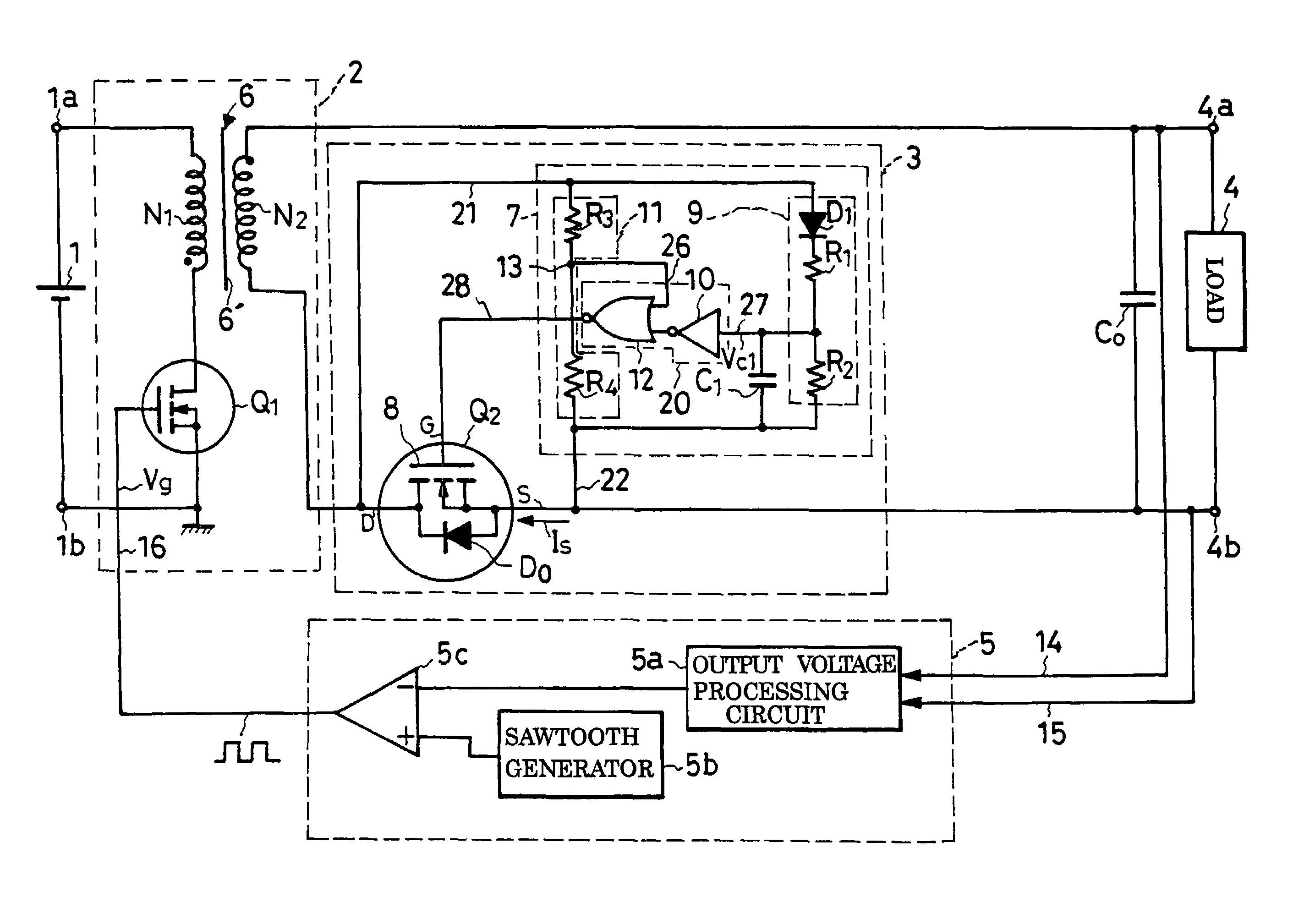
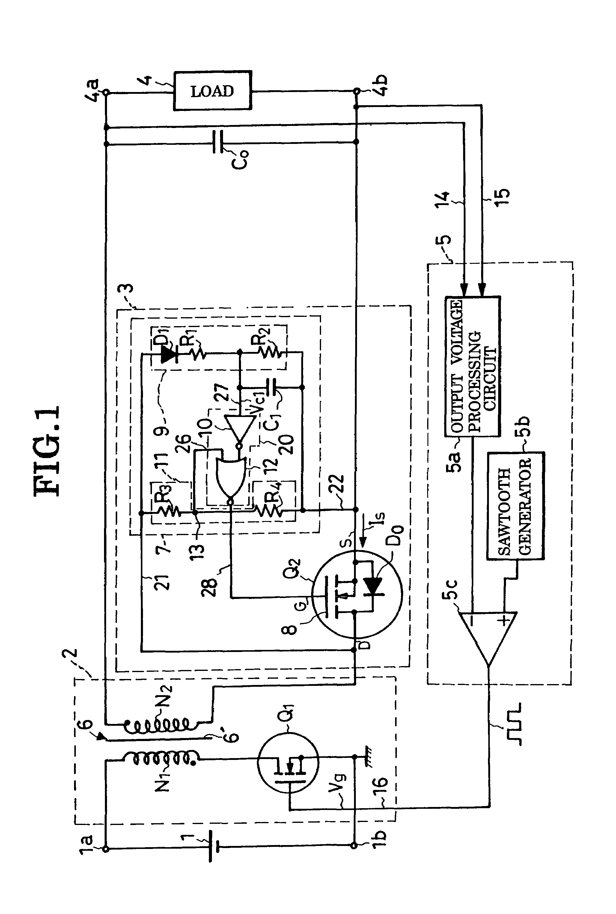
[0076]The second preferred form of switching-mode power supply shown in FIG. 3 incorporates a modified synchronous rectifier circuit 3a and is identical with the FIG. 1 embodiment in all the other details of construction. The modified synchronous rectifier 3a differs from its FIG. 1 counterpart 3 only in its synchronous rectifier control circuit 7a, which in turn differs from its FIG. 1 counterpart 7 only in its charge / discharge circuit 9a.

[0077]The modified charge / discharge circuit 9a features a discharge circuit of a resistor R2′ and diode D2 interconnected in series, instead of the discharge resistor R2 of the FIG. 1 charge / discharge circuit 9. This discharge circuit is connected in parallel with the charge circuit comprised of the diode D1 and resistor R1 which are interconnected in series as in the FIG. 1 embodiment. The charge diode D1 and discharge diode D2 are opposite in polarity.

[0078]The second preferred form of switching-mode power supply operates like that of F...


PUM


Abstract

A DC-to-DC converter incorporates a transformer having a primary winding connected to a pair of DC input terminals via an active switch, which turns on and off under the control of a feedback circuit, and a secondary winding connected to a pair of DC output terminals via a synchronous rectifier and a smoothing capacitor. The synchronous rectifier is a parallel connection of a synchronous rectifier switch and a diode. A synchronous rectifier control circuit is connected to the synchronous rectifier switch for causing conduction therethrough while the active switch is off. The synchronous rectifier control circuit comprises a capacitor for determination of the conducting periods of the synchronous rectifier switch, and a logic network for on / off control of the synchronous rectifier switch according to whether the active switch is on or off and whether the capacitor voltage is higher than a predefined threshold or not.

Description

CROSS REFERNCE TO RELATED APPLICATIONS[0001]This is a continuation of Application PCT / JP2004 / 014075, filed Sep. 27, 2004, which claims priority to Japanese Patent Application No. 2003-340758 filed Sep. 30, 2003.BACKGROUND OF THE INVENTION[0002]This invention relates to an electronic power supply unit known as the switching-mode power supply, incorporating a switching regulator whereby the load current is switched rapidly on and off for output voltage stabilization. More specifically, the invention pertains to such a power supply of the kind having a synchronous rectifier circuit.[0003]A typical conventional switching-mode power supply with a flyback DC-to-DC converter includes a transformer having a primary winding coupled to the pair of DC input terminals via an active switch, and a secondary winding coupled to the pair of DC output terminals via a rectifying diode and smoothing capacitor. The DC input voltage is turned on and off as the active switch is driven by pulses that have ...

Claims


Application Information

Patent Timeline
Patent Type & Authority Patents(United States)
IPC IPC(8): H02M3/335
CPCH02M3/33592Y02B70/1475Y02B70/10
Inventor KYONO, YOICHI
Owner SANKEN ELECTRIC CO LTD
Why Eureka
Try Eureka