Receiver and its tracking adjusting method

a tracking adjustment and receiver technology, applied in the field of receivers, can solve the problems of weak to the fluctuation of a supply voltage, difficult temperature compensation, time-consuming tracking adjustment, etc., and achieve the effect of optimal offset voltage, easy setting of offset voltage, and easy reduction of tracking error

Inactive Publication Date: 2006-10-10
RICOH KK
View PDF10 Cites 6 Cited by
  • Summary
  • Abstract
  • Description
  • Claims
  • Application Information

AI Technical Summary

Benefits of technology

[0010]The present invention is created in view of such points, and aims at providing a receiver and its tracking adjusting method which can shorten the time required for tracking adjustment, does not require temperature compensation, and can prevent a tracking error from increasing because of the fluctuation of a supply voltage.

Problems solved by technology

By the way, in the case of setting a tuning frequency of the high frequency receiving circuit 202 with interlocking with an oscillation frequency of the local oscillator 204 by using the conventional system mentioned above, there have been problems: (1) a tracking adjustment takes time, (2) temperature compensation is difficult, and (3) it is weak to the fluctuation of a supply voltage.
Since such measurement is required every tuned voltage, it takes much time for the tracking adjustment.
Thus, since only the tuning frequency changes with interlocking with a temperature change but the frequency of the local oscillation signal does not change, a tracking error increases in connection with the temperature change.
Although it is necessary to equip with a temperature compensation circuit newly in order to avoid such inconvenience, it is not easy to prevent the increase of the tracking error by performing temperature compensation over the entire range of the tuning frequency, and further, there newly arises a problem that a circuit scale become large.
Furthermore, when a supply voltage of the receiver shown in FIG. 8 fluctuates, for example, when a drive voltage drops in a pocket receiver driven by a battery, a car radio driven by an vehicle-mounted battery, or the like, an output voltage of the DAC 216 becomes low with interlocking with the drop of the supply voltage, and hence, a tracking error becomes large since a tuned voltage drops even if the MPU 210 intends to set a desired tuning frequency.

Method used


Image

  • Receiver and its tracking adjusting method
  • Receiver and its tracking adjusting method
  • Receiver and its tracking adjusting method

Examples


Embodiment Construction

[0031]Hereafter, an FM receiver according to an embodiment where the present invention is applied will be described with referring to drawings.

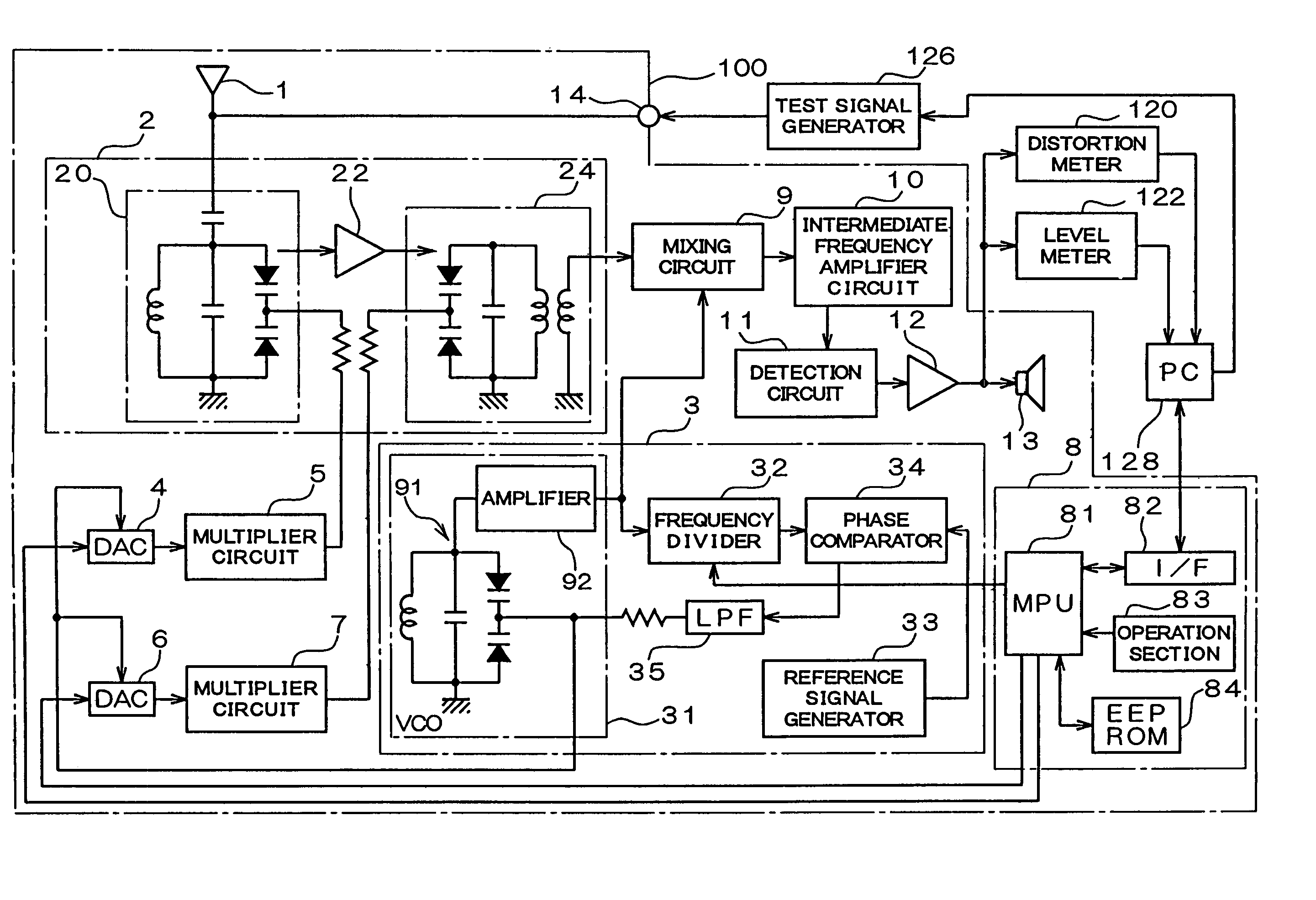
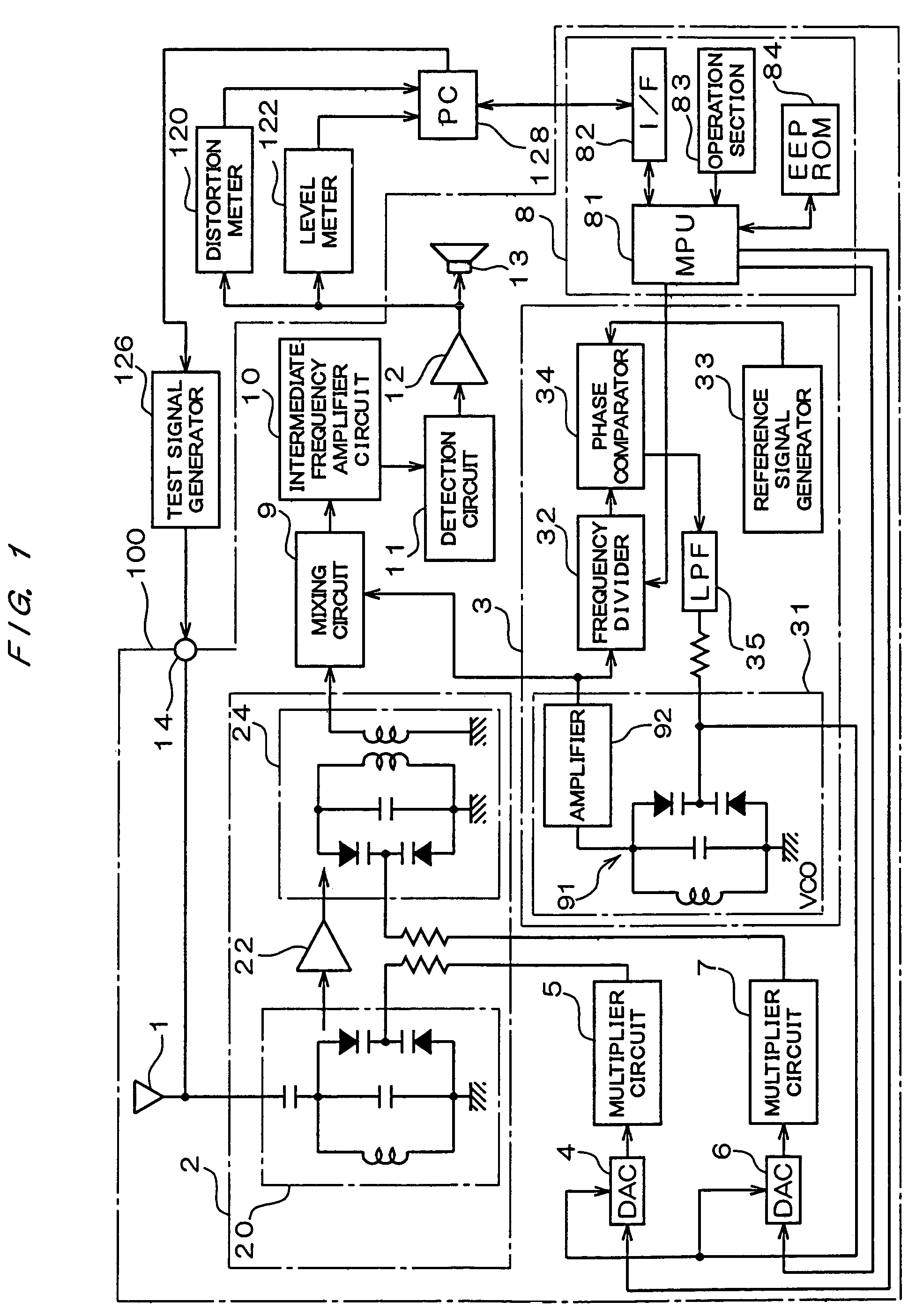
[0032]FIG. 1 is a diagram showing the structure of an FM receiver of this embodiment. An FM receiver 100 shown in this diagram is constituted by including an antenna 1, an high frequency receiving circuit 2, a local oscillator 3, two digital-to-analog converter (DAC) 4 and 6, two multiplier circuits 5 and 7, a control section 8, a mixing circuit 9, an intermediate frequency amplifier circuit 10, a detection circuit 11, a low frequency amplifier 12, and a speaker 13.

[0033]The high frequency receiving circuit 2 performs high frequency amplification of a signal after tuning while performing the tuning operation of selectively passing only a component near a predetermined tuning frequency to a broadcast wave inputted from the antenna 1, and is constituted by including two high-frequency tuning circuits 20 and 24, and a high frequency amplifier 22...


PUM


Abstract

A receiver such that the period required for tracking adjustment, temperature compensation is not needed, and tracking errors due to fluctuation of the power supply voltage are prevented from increasing, and a tracking adjusting method for the receiver. A DAC 4 generates a voltage according to the value of data (Do) inputted from an MPU 81 by using a control voltage outputted from a low-pass filter 35 in a local oscillator 3 as a reference voltage used during digital-analog conversion. A multiplier circuit 5 analog-multiplies the output voltage of the DAC 4 by a predetermined multiplier. The output voltage of the multiplier circuit 5 is applied as a tuning voltage to a high-frequency tuning circuit 20. In an EEPROM 84 stored is the value of the input data (Do) of the DAC 4 which has been measured in advance and corresponds to the tuned voltage of when the tracking error is the minimum at the central value of the local oscillation frequency, and the MPU 81 reads the data (Do) from the EEPROM 84 and inputs it to the DAC 4.

Description

TECHNICAL FIELD[0001]The present invention relates to a receiver which adopts a superheterodyne system, and its tracking adjusting method.BACKGROUND ART[0002]Generally, in receivers which receive broadcast waves such as AM broadcast and FM broadcast, a superheterodyne system is adopted as a receiving system. The superheterodyne system is a receiving system which converts a received broadcast signal into an intermediate frequency signal, which has a fixed frequency independent of an frequency of a received signal (receive frequency), by mixing a predetermined local oscillation signal to the received broadcast signal, and reproduces a sound signal by performing detection processing, amplification, etc. after that, and has a feature that it is superior to other receiving systems in sensitivity, selectivity, etc.[0003]FIG. 8 is a diagram showing the structure of a conventional receiver which adopts the superheterodyne system. The conventional receiver shown in this diagram is constitute...

Claims


Application Information

Patent Timeline
Patent Type & Authority Patents(United States)
IPC IPC(8): H04B1/18H03J1/00H03J3/24H03L7/099H03L7/18H04B17/00
CPCH03J1/005H03J3/24H04B17/20H03L7/099H03L7/0805H03L7/18
Inventor MIYAGI, HIROSHI
Owner RICOH KK
Why Eureka
Try Eureka