
Sanitary manifold system and method for hygienically dispensing fluids

a manifold and fluid technology, applied in the direction of mechanical equipment, transportation and packaging, cleaning using liquids, etc., can solve the problems of more difficult parts of the container that interface with the dispensing unit, and achieve the effect of preventing backflow of fluid, promoting the return of cleaning or rinsing fluid, and efficient flushing of the fitting and portion

Inactive Publication Date: 2006-10-17
NESTEC SA
View PDF11 Cites 13 Cited by
  • Summary
  • Abstract
  • Description
  • Claims
  • Application Information

AI Technical Summary

Benefits of technology

[0011]As a result of this configuration of the manifold system, it is possible to clean or rinse in the most critical part of the container, more particularly, within the terminal connecting portion of the container, so that microbial growth can successfully be prevented in this area. Indeed, although it is relatively easy to retain the source of sensitive fluid relatively free from contamination, it is more difficult with parts of the container that interfaces with the dispensing unit.
[0012]As other benefits of the invention, the container, the connection between the container and the manifold system can be simplified and significant savings can be made on the packaging cost.
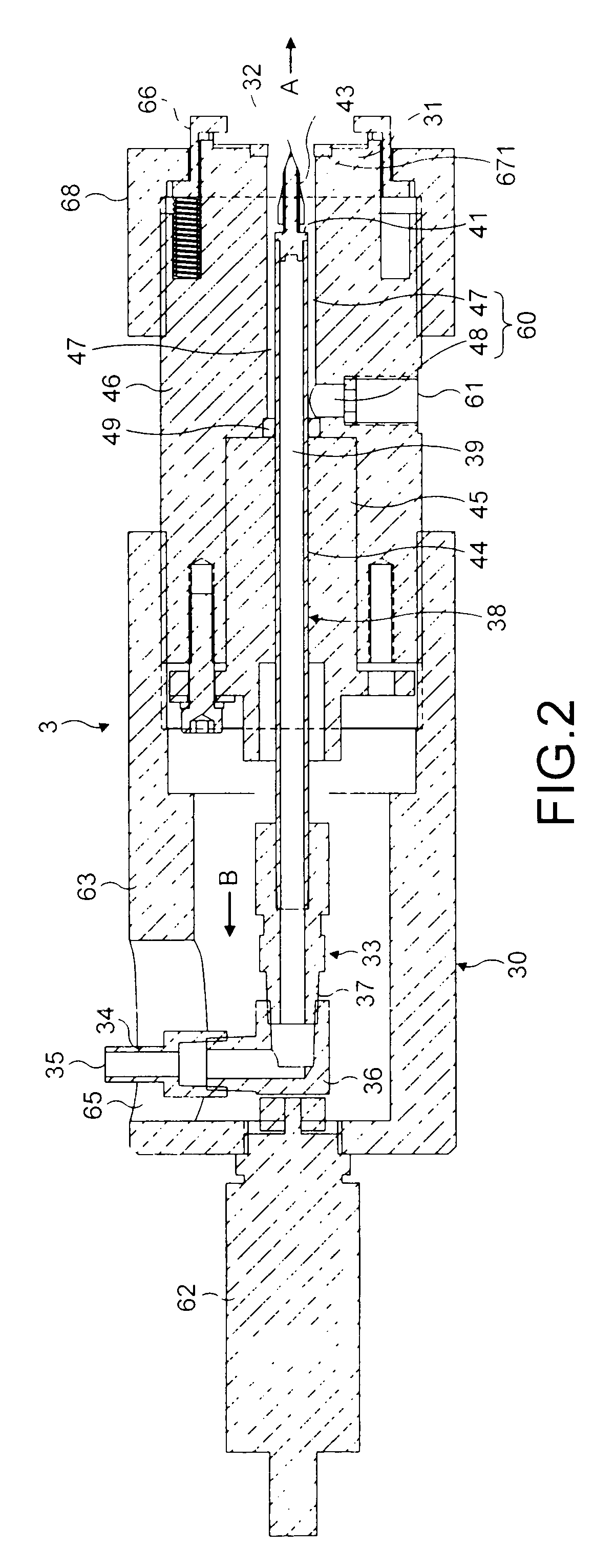
[0014]In the retracted position, the interface port is left open for allowing the flow of the beverage or food components to evacuate out of the container through a portion of hose and the terminal connecting portion, then, through the discharge line. In the inserted position of the projection, the internal part of the terminal connecting portion including a certain portion of hose can thus be cleaned or rinsed in a very effective way. This moving arrangement also participates to the simplification of the container's packaging since the terminal connecting portion of the container can be made simpler as there is no requirement for specific built-in valve means to prevent backflow.
[0017]In order to promote return of the cleaning or rinsing fluid on the internal peripheral surface of the terminal connecting portion of the container, the discharge line extends from the interface port to a discharge outlet, at least partially, by a chamber located about the peripheral surface of the projection member. Hence, after the cleaning fluid has flowed due to a sufficient flow velocity, within the terminal connecting portion of the container up to a pinched point of the hose, the internal surfaces of the terminal connecting portion of the container can be properly wiped by the annular return flow created to properly evacuate the contaminants and / or solid residues in direction of the discharge line.
[0018]In a preferred aspect of the invention, an external valve of the device is provided to engage the hose of the container, in a region proximate the interface port, to maintain the upstream portion of the hose and package sterile and isolate them from the terminal connecting portion, such as the fitment and its short connected portion of hose, so as to allow cleaning or rinsing of this downstream portion up to the closing point of the valve. Therefore, it is possible to very efficiently flush the fitment and portion of tube up to the closing point and thus eliminate the possibility for micro-organisms to freely grow in this area. This arrangement also enables to maintain aseptic or sterile conditions in the container and upstream the valve after the container's fitment has securely been connected at the interface port without the requirement for complex connections and valve means usually provided to prevent backflow of fluid or contaminants within the container.
[0019]The valve is preferably a pinched valve acting externally on the portion of hose. Since, there is no direct contact between the valve and the microbiologically sensitive fluid, the risks of contamination and growth are prevented and the risks of food residue accumulating in this area are reduced.

Problems solved by technology

Indeed, although it is relatively easy to retain the source of sensitive fluid relatively free from contamination, it is more difficult with parts of the container that interfaces with the dispensing unit.

Method used


Image

  • Sanitary manifold system and method for hygienically dispensing fluids
  • Sanitary manifold system and method for hygienically dispensing fluids
  • Sanitary manifold system and method for hygienically dispensing fluids

Examples


Embodiment Construction

[0043]The present description is presented to enable any person of ordinary skill in the art to make and use the invention. Various modifications to the preferred embodiment will readily be apparent to those of ordinary skill in the art, and the disclosure set forth may be applicable to other embodiments and applications without departing from the spirit of the invention and the claims appended hereto.

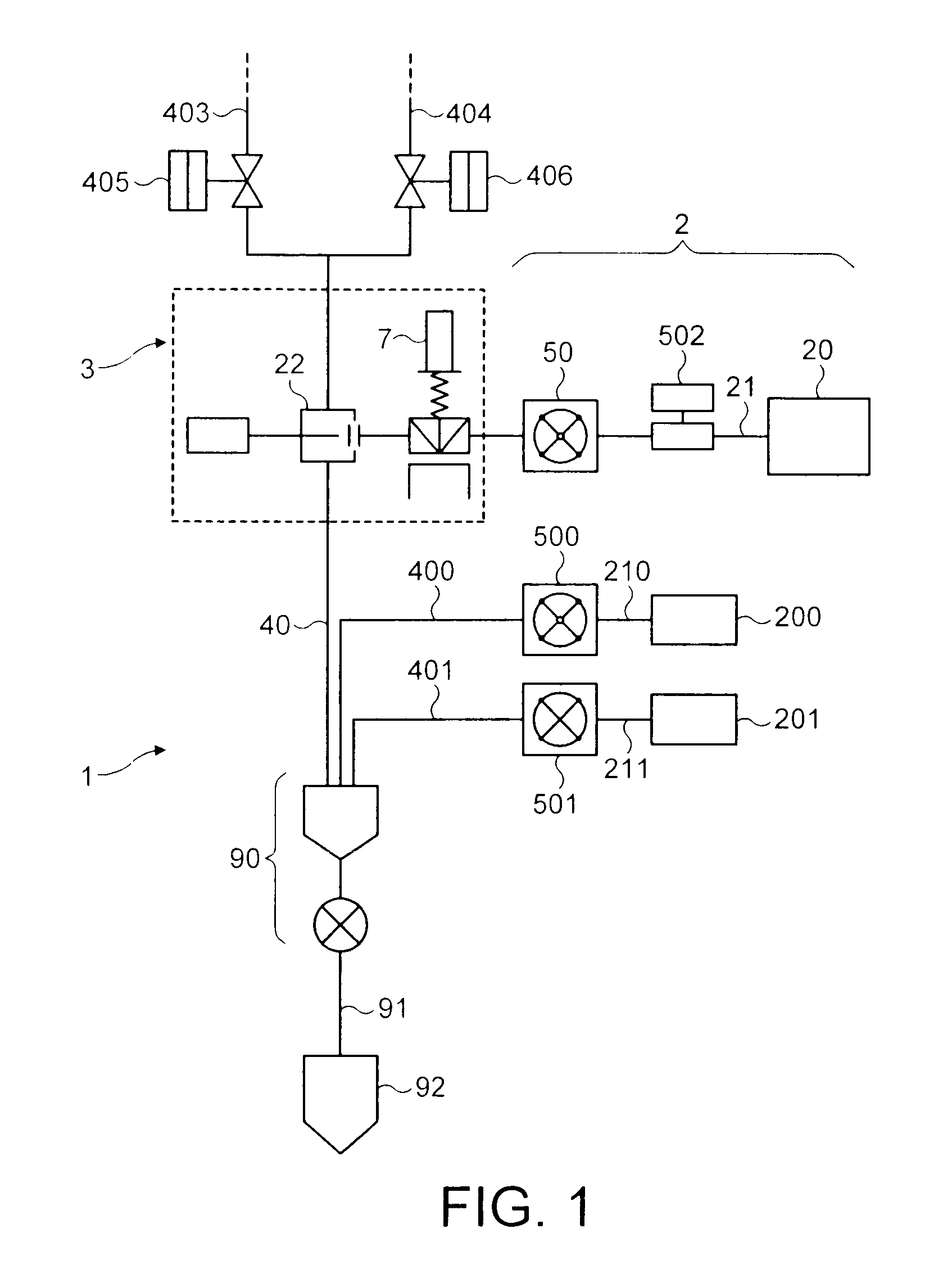
[0044]With reference first of all to FIG. 1, one can see a simplified dispensing device 1 adapted to provide a variety of hot and cold beverages by the combination of various concentrates, including microbiologically sensitive components such as milk concentrate, with water without the requirement for a refrigeration unit. For instance, the dispensing device 1 of the invention can deliver whitened hot or cold beverages on demand such as cappuccino, latte, coffee milk, chocolate or alternatively non-whitened beverages such as black coffee, tea, etc.

[0045]The concentrates are generally s...


PUM


Abstract

The present invention relates to the dispensing of a microbiologically sensitive fluid, in particular low acid food fluid, in a hygienic manner so as to avoid micro-organism growth in the line dispensing the fluid as well as in any mechanical components of a dispensing unit that may enter into contact with the fluid. The invention relates to a device for hygienically supplying microbiologically sensitive fluid from a removable container that has a terminal connecting portion to a dispensing unit. The device includes a coupling mechanism adapted to connect the terminal connecting portion and a component for delivering a cleaning or rinsing fluid within the terminal connecting portion.

Description

FIELD OF THE INVENTION[0001]The present invention relates to the dispensing of a microbiologically sensitive fluid, in particular low acid food fluid, in a hygienic manner so as to avoid micro-organism growth in the line that dispenses the fluid as well as in any mechanical components of a dispensing unit that come into contact with the fluid. More particularly, the invention can be used for delivering with a high degree of food safety shelf stable milk-based concentrates from a dispensing unit to reconstitute a whitened beverage.BACKGROUND ART[0002]In the foodservice area, post-mix beverage dispensers are known which mix a concentrate or syrup with several measures of water and then dispense the mixture on demand to reconstitute a hot or cold beverage such as juice, carbonated sodas, coffee or tea. Coffee, tea or soda concentrates are relatively easy and safe to store in bags at ambient temperature as they usually contain a high amount of solids and / or sugar, a low pH and a low wat...

Claims


Application Information

Patent Timeline
IPC IPC(8): B08B9/00B08B9/02B08B9/023B08B9/027A47J31/44B08B3/04B67D1/07F16L55/10
CPCB67D1/07B08B9/0321Y10T137/4259
Inventor CARHUFF, PETER W.DICKINSON, EDWARD L.HARVEY, ANDREW C.KOLVEK, EDWARD M.MASU, TAKESHI
Owner NESTEC SA
Learn More