Installation structure for electric rotating machine in motor vehicle

a technology of installation structure and electric rotating machine, which is applied in the direction of propulsion parts, electric propulsion mounting, transportation and packaging, etc., can solve the problems of increasing production cost and production steps, reducing design freedom, and change is not preferable, so as to increase design restrictions and reduce design freedom

Inactive Publication Date: 2006-10-17
NISSAN MOTOR CO LTD
View PDF22 Cites 42 Cited by
  • Summary
  • Abstract
  • Description
  • Claims
  • Application Information

AI Technical Summary

Benefits of technology

[0003]However, in the above conventional installation structure for the electric rotating machine for the wheel, a considerably large-sized unit is disposed inside the wheel. The housing of the drive unit is arranged to also serve as a bearing support member (so-called knuckle) to which control arms of the suspension and parts of a shock absorber are to be installed. Accordingly, in such a conventional installation structure, the considerably large-sized unit is installed inside the wheel in a location where parts such as an electric motor are not installed in a motor vehicle which is driven by an engine and extensively sold in the market. This requires to modify the shape or the like of existing parts (such as the suspension) located around the wheel and to increase restrictions in design for such parts thereby decreasing a freedom in design.

Problems solved by technology

This requires to modify the shape or the like of existing parts (such as the suspension) located around the wheel and to increase restrictions in design for such parts thereby decreasing a freedom in design.
Therefore, it seems that a production cost and the number of production steps are increased.
Additionally, such a change is not preferable from the viewpoint of improving a production efficiency by standardization of assembly line.

Method used


Image

  • Installation structure for electric rotating machine in motor vehicle
  • Installation structure for electric rotating machine in motor vehicle
  • Installation structure for electric rotating machine in motor vehicle

Examples


first embodiment

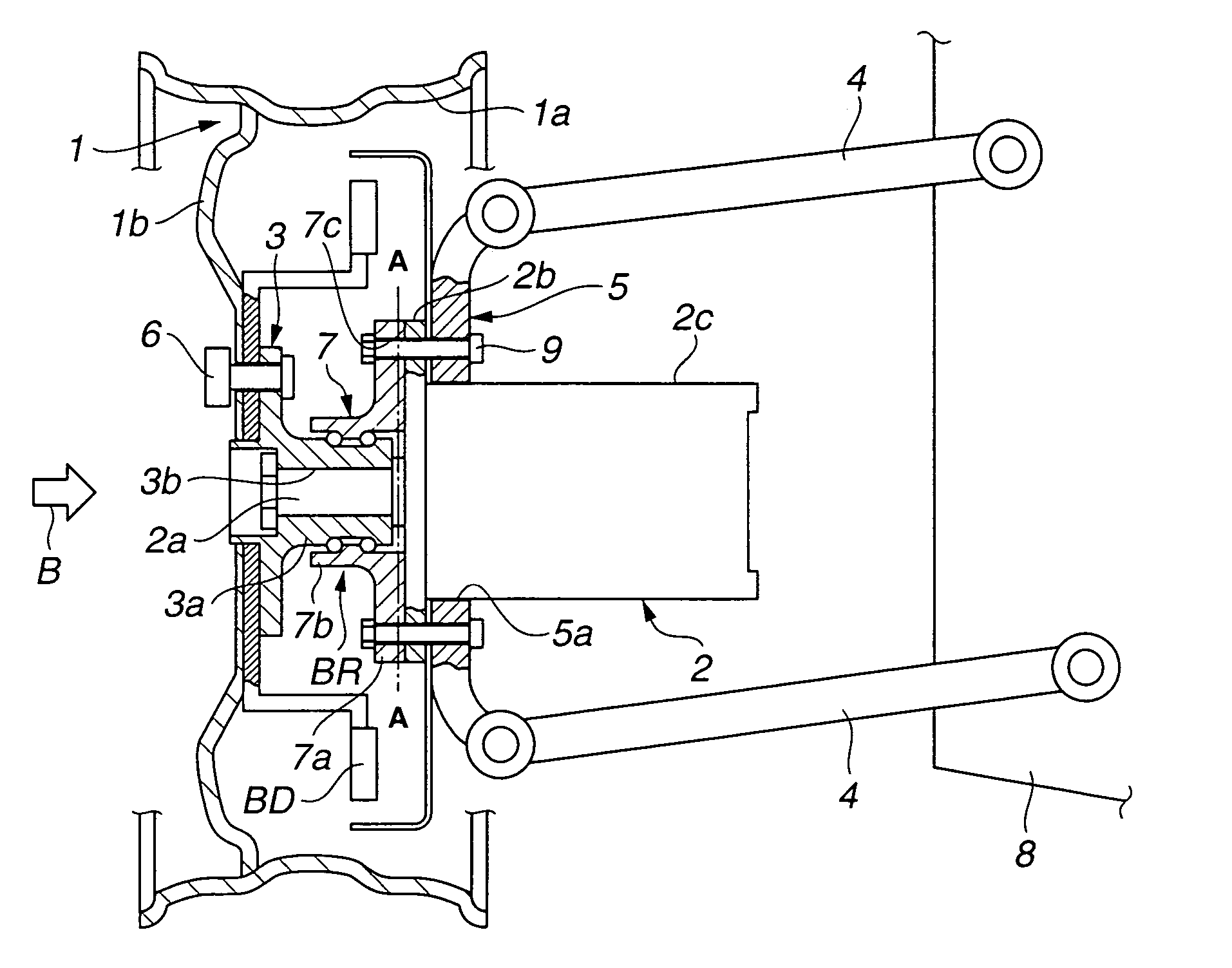
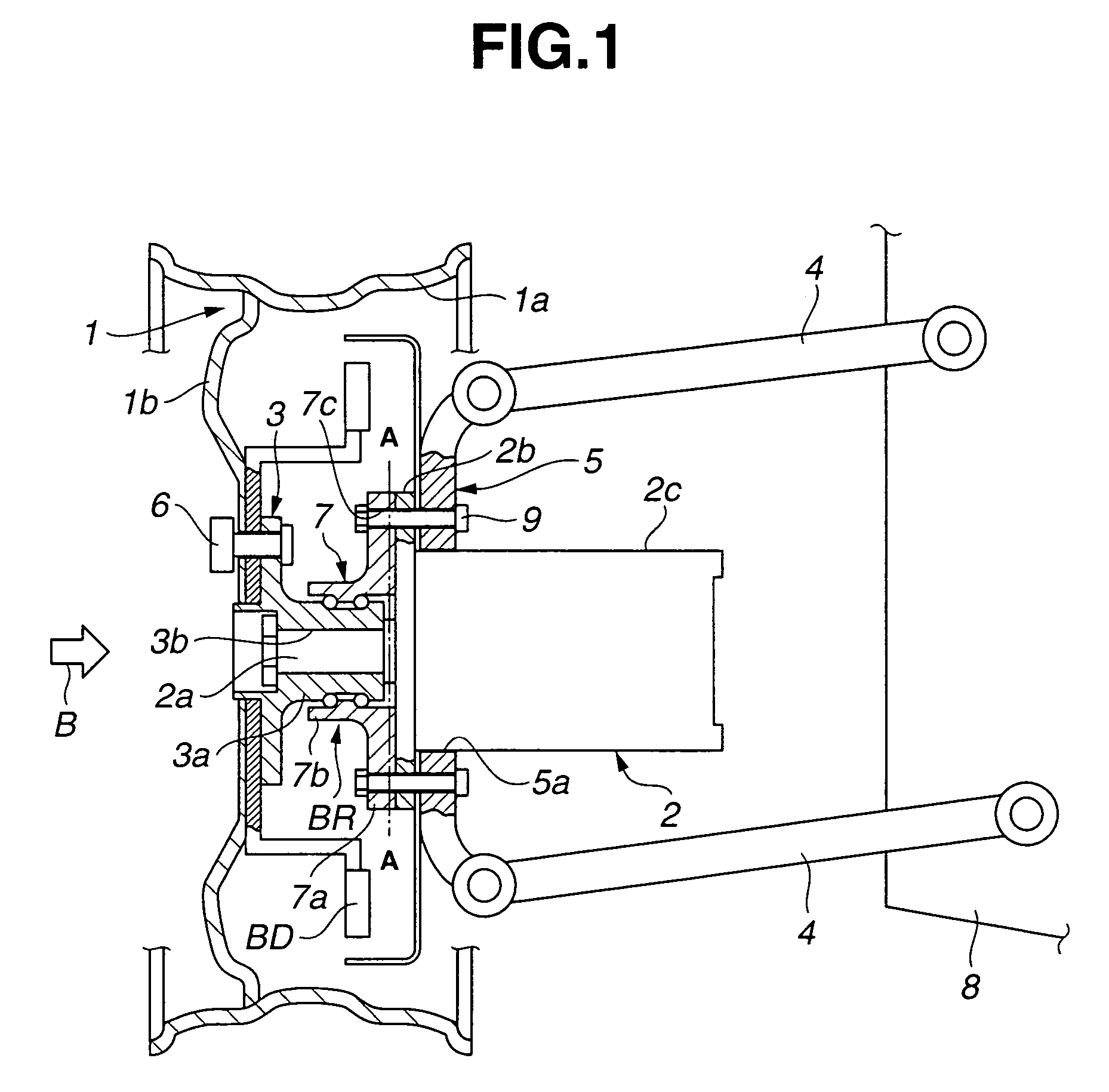
[0016]Referring now to FIG. 1, an installation structure for an electric motor, according to the present invention is illustrated in combination with an automotive vehicle as a motor vehicle. The automotive vehicle includes road wheels 1 one of which is shown. Wheel 1 is electrically driven by an electric motor 2 as an electric rotating machine which is installed generally inside wheel 1.

[0017]In the installation structure of this embodiment, wheel hub 3 is fixed to and rotatable with wheel 1. Additionally, ball bearing BR is provided to rotatably support wheel hub 3. Bearing support member (or so-called knuckle) 5 is connected to suspension 4 which is installed to vehicle body 8 of the automotive vehicle. Electric motor 2 has power output shaft 2a and provided with flange 2b for location of the electric motor in a direction of axis of the power output shaft. Flange is brought into contact with a wheel(1)-side section of bearing support member 5. Additionally, power output shaft 2a ...

second embodiment

[0033]FIG. 4 illustrates the installation structure for the electric rotating machine for the wheel, according to the present invention, which is similar to the above-discussed embodiment shown in FIG. 1 mainly with the exception that electric motor 2 is formed integral with ball bearing BR for supporting wheel hub 3.

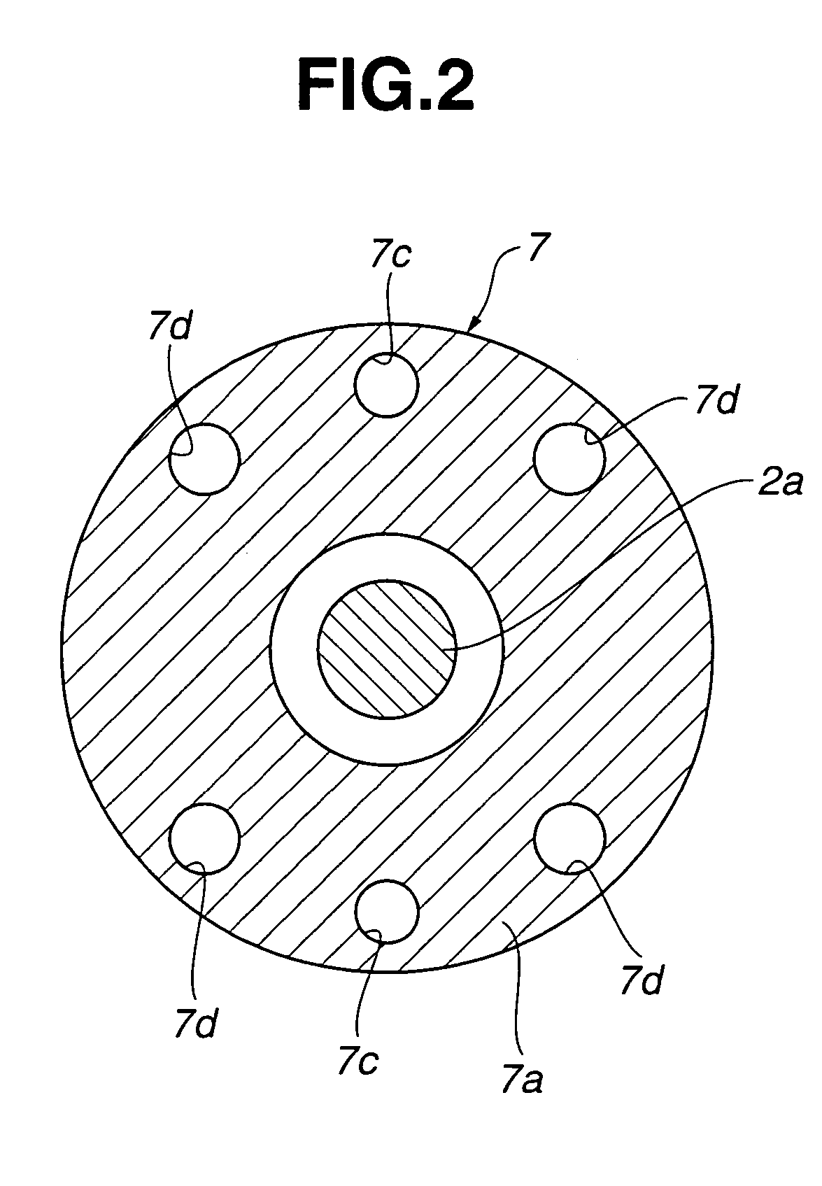
[0034]Specifically, in this embodiment, bearing outer member 7 (shown in FIG. 1) in the embodiment of FIG. 1 is formed integral with housing 2d of electric motor 2. This provides bearing-flange section 2e in which flange section 7a (as shown in FIG. 1) and flange section 2b of electric motor 2 (as shown in FIG. 1) in the first embodiment are integrally connected.

[0035]In this embodiment, electric motor 2 is similar in function to that 2 in the first embodiment. Accordingly, electric motor 2 is general DC motor and has power output shaft (or power transmission shaft) 2a. A rotor R is fixedly mounted on the power output shaft 2a so as to be rotatable with the power output...


PUM


Abstract

An installation structure for an electric rotating machine such as an electric motor to a wheel of a motor vehicle. The installation structure comprises a wheel hub fixed to and rotatable with the wheel. A bearing through which the wheel hub is rotatably supported is provided. A suspension is installed between a vehicle body of the motor vehicle and the wheel. A bearing support member is connected to a wheel-side section of the suspension and supports the bearing. In the above installation structure, the electric rotating machine includes a power output shaft which is in fit with the wheel hub, and a flange for location of the electric rotating machine in a direction of axis of the power output shaft, the flange being brought into contact with a wheel-side section of the bearing support member.

Description

BACKGROUND OF THE INVENTION[0001]This invention relates to improvements in an installation structure for an electric rotating machine such as an electric motor provided to a wheel of a motor vehicle such as an electric vehicle.[0002]Hitherto, an installation structure for an electric motor or the like to be disposed inside a wheel of a motor vehicle such as an electric vehicle has been proposed in Japanese Patent Provisional Publication No. 2001-32888, and arranged as follows: The electric motor is encased in a housing so as to constitute a drive unit. The vehicle body-side section of the housing is suspended through a suspension to a vehicle body. The wheel-side section of the housing is rotatably mounted on a wheel hub through a bearing in such a manner that a power output shaft (power transmission shaft) of the electric motor is fixed to a wheel hub which is fixed to a rim section of the wheel.SUMMARY OF THE INVENTION[0003]However, in the above conventional installation structure...

Claims


Application Information

Patent Timeline
Patent Type & Authority Patents(United States)
IPC IPC(8): B60K1/00B60B35/16B60K7/00
CPCB60K7/0007B60G2200/144B60G2200/422B60G2204/30B60G2300/50B60K2007/0038B60K2007/0092
Inventor AJIRO, KEIGOTSUNEHARA, HIROSHI
Owner NISSAN MOTOR CO LTD
Why Eureka
Try Eureka