Segmented synchronizer clutch

a synchronizer clutch and segmented technology, applied in the direction of interengaging clutches, friction clutches, clutches, etc., can solve the problems of jiggling of the transmission in the gear, and achieve the effect of convenient assembly

Active Publication Date: 2006-10-17
SULZER FRICTION SYST US
View PDF16 Cites 24 Cited by
  • Summary
  • Abstract
  • Description
  • Claims
  • Application Information

AI Technical Summary

Benefits of technology

[0012]Drive coupling between the or each synchronizer ring and the other of the hub and the gear is preferably effected by means of a plurality of radial tabs formed on the segments which engage radial pockets formed in the other of the hub and the gear. ...

Problems solved by technology

These conventional synchronizers have the disadvantage, however, that if the cone surfaces on the gear and the synchronizer ring are formed with taper angles that are too small, that is, which are shallower than the friction angles determi...

Method used


Image

  • Segmented synchronizer clutch
  • Segmented synchronizer clutch
  • Segmented synchronizer clutch

Examples


Embodiment Construction

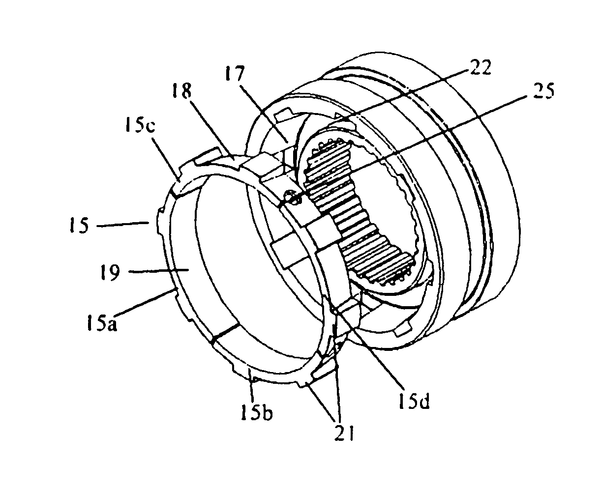
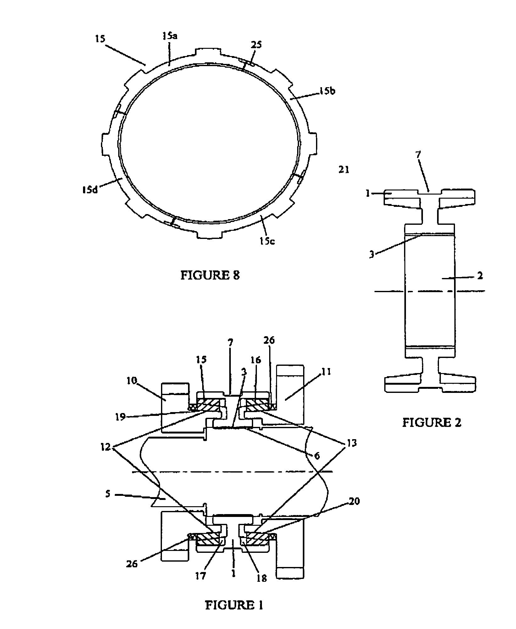
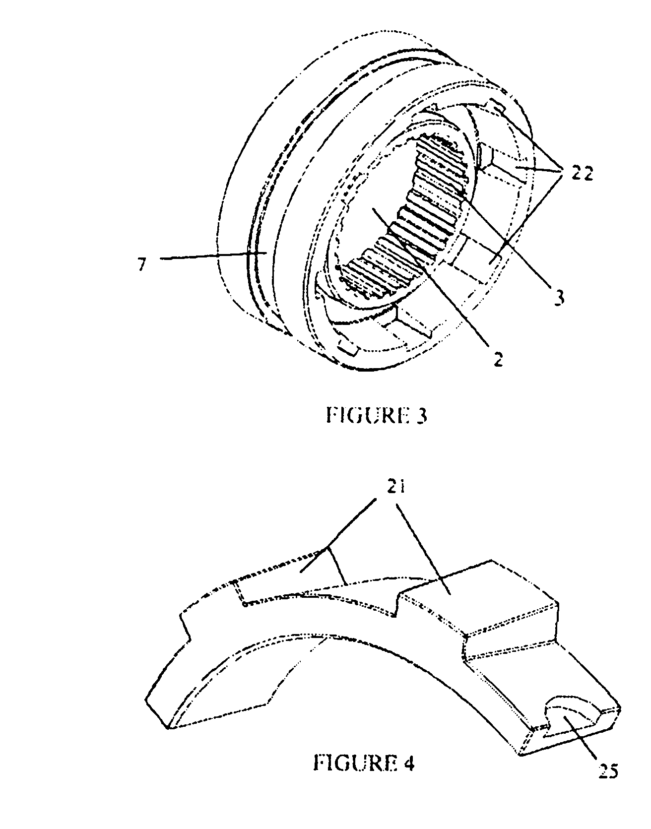
[0027]Referring first to FIGS. 1 and 2, there is shown a sectional side view of a bi-directional segmented synchronizing clutch assembly according to the invention. The assembly includes a hub 1 having a central opening 2 on the inner circumferential surface of which is formed a plurality of teeth 3 as shown more clearly in FIG. 3. A shaft member 5 extends through said opening 2 in the hub 1 and has a plurality of external splines or teeth 6 which engage with the teeth 3 of said opening 2 so that the hub 2 is secured to and rotates with the shaft 5 whilst permitting axially movement of the hub 1 along the shaft. Such axial movement of the hub 1 is effected by means of a linkage arm (not shown) which engages a circumferential groove 7 formed in the outer surface of the hub 1 and may be achieved manually, hydraulically, electronically, electro-magnetically or by any other well known means.

[0028]The hub 1 is positioned on the shaft 5 between a pair of gears 10, 11 having different gear...


PUM


Abstract

A synchronizer clutch assembly includes a clutch hub which is axially movably mounted on a shaft, a gear which is axially spaced from the hub and which is journally mounted on the shaft and rotatable independent thereof, one of the hub or the gear having a conical friction surface formed thereon, and a synchronizer ring positioned between the hub and the gear. The synchronizer ring is coupled to the hub or the gear for rotation therewith and has a complementary conical friction surface formed thereon which is engageable with the conical friction surface on the hub or the gear. The synchronizer ring is composed of a plurality of separate arcuate segments arranged in a ring, which are movable between a first expanded configuration and a second, contracted configuration.

Description

BACKGROUND OF THE INVENTION[0001]The present invention relates to automotive transmissions and more particularly to synchronizer clutches for controlling changes in transmission gearing.[0002]Synchronizer clutch assemblies are used to facilitate the smooth engagement of meshing teeth during changes of gears in a transmission. A typical assembly includes a hub positioned between two gears of different pitch diameter, the hub having a central opening in which are formed a plurality of teeth for drivingly mounting the hub on a drive shaft. A clutch sleeve with internal clutch teeth is mounted for axial sliding movement on the hub, and each gear also carries corresponding external sleeve teeth which are engageable by the inner teeth of the sleeve in order to create a drive path from the shaft, through the hub and sleeve to the gear. Each gear also carries an external cone clutch surface which is engageable by a complementary internal cone clutch surface formed on a synchronizer ring dis...

Claims


Application Information

Patent Timeline
IPC IPC(8): F16D13/16F16D13/26
CPCF16D23/025F16D23/06F16D2023/0681
Inventor SKIPPER, GARY I.ROBERTS, KEITH
Owner SULZER FRICTION SYST US
Why Eureka
Try Eureka