Rugged foam buoyancy modules and method of manufacture

a foam and buoyancy module technology, applied in the direction of sealing/packing, mechanical equipment, borehole/well accessories, etc., can solve the problems of affecting the buoyancy material, the module is often subject to extreme handling, and the handling is not easy to be damaged during handling and installation, so as to improve the ruggedness of the buoyancy material, increase the bending strength, and increase the reinforcement

Inactive Publication Date: 2006-10-17
CUMING CORP
View PDF36 Cites 28 Cited by
  • Summary
  • Abstract
  • Description
  • Claims
  • Application Information

AI Technical Summary

Benefits of technology

[0008]Advantageously, the buoyancy module has a plurality of different layers, wherein the components of greatest strength and density are located on the outside. The multi-component system improves ruggedness of the buoyancy material, and provides increased reinforcement at locations subject to increased bending strengths, and provides a buoyancy module of longer life. In addition the buoyancy module may also include steel support members where bolting loads and other forces are brought to bear when parts are attached.

Problems solved by technology

A problem with these prior art buoyancy modules is that they are susceptible to damage during handling and installation.
For example, when buoyancy modules are used for risers in offshore oil rigs, the modules are often subject to extreme handling.
Impacts to the modules can damage and / or fracture the single outer layer, and also damage the macrospheres within the single outer layer.
Hence, prior art buoyancy material can often be damaged during handling and installation, which reduces their service life.

Method used


Image

  • Rugged foam buoyancy modules and method of manufacture
  • Rugged foam buoyancy modules and method of manufacture
  • Rugged foam buoyancy modules and method of manufacture

Examples


Embodiment Construction

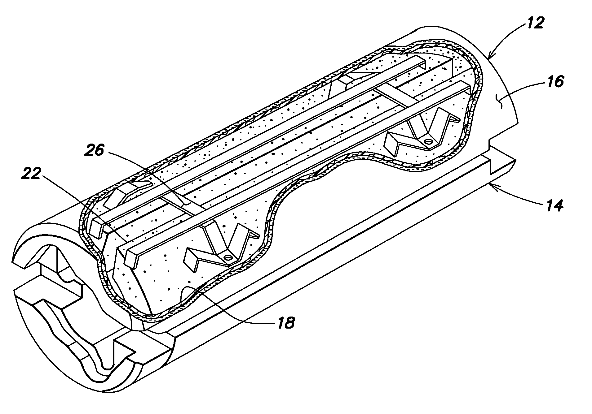
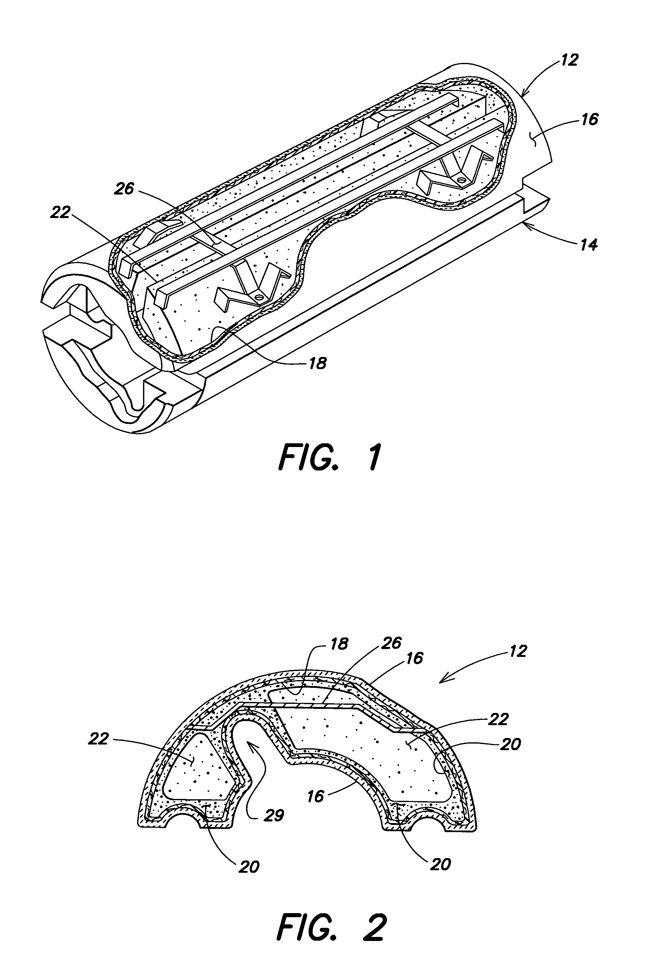
[0013]FIG. 1 is a partially cut-a-way pictorial illustration of buoyancy modules 12, 14 that can be mounted around a flowline (not shown). FIG. 2 is a cross-sectional illustration of the buoyancy module of FIG. 1. Referring to FIGS. 1 and 2, each buoyancy module 12, 14 includes a fiberglass outer skin 16 (e.g., e-glass) that is backed by a fibrous plastic liner 18. The fibrous plastic liner 18 provides additional impact strength to the outer surface 16, and is preferably a tough elastic (e.g., stretchy) type of plastic that does not break. Therefore, even if there is a fracture of the fiberglass outer skin 16, the fibrous plastic liner 18 will not break and absorbs shock, thus preventing the fracture from increasing and holding the buoyancy modules' components together. The fibrous plastic liner 18 may include a non-woven random matted material made of nylon fiber. The liner 18 may be for example about 0.25 inches thick. The fiber is preferably a coarse (e.g., 1 mm in diameter) indu...


PUM

PropertyMeasurementUnit
diameteraaaaaaaaaa
thickaaaaaaaaaa
diameteraaaaaaaaaa

Abstract

A buoyancy module comprises a multi-layer outer protective shell that has an exterior surface and an interior surface. A first layer of foam buoyancy material is located adjacent to the interior surface. A second layer of foam buoyancy material that includes macrospheres and syntactic foam is surrounded by the first layer of foam buoyancy material. The multi-layer outer protective shell can include a layer of fiberglass backed by a fibrous plastic liner. In this embodiment, the layer of fiberglass provides the exterior surface of the multi-layer outer protective shell, while the fibrous plastic liner provides the interior surface of the protective shell. The second layer of foam buoyancy material can be a precast material. The precast material can include for example macrospheres and syntactic foam. The first layer of foam buoyancy material is preferably a stronger layer than the second layer of foam buoyancy material. Advantageously, the buoyancy module has a plurality of different layers, wherein the components of greatest strength and density are located on the outside. The multi-component system improves ruggedness of the buoyancy material, and provides increased reinforcement at locations subject to increased bending strengths, and provides a buoyancy module of longer life. In addition the buoyancy module may also include steel support members where bolting loads and other forces are brought to bear when parts are attached.

Description

CROSS REFERENCE TO RELATED APPLICATIONS[0001]This application claims priority from the provisional application designated Ser. No. 60 / 332,250 filed Nov. 14, 2001 and entitled “Method for Making Syntactic Foam Buoyancy Modules of Superior Strength and Ruggedness”. This application is hereby incorporated by reference.BACKGROUND OF THE INVENTION[0002]The invention relates to foam buoyancy modules, and in particular to multilayered / multi-component buoyancy modules with improved ruggedness.[0003]The use of syntactic foam in buoyancy modules is well known. Buoyancy modules have generally included a single outer protective layer that surrounds a monolithic arrangement of syntactic foam. A problem with these prior art buoyancy modules is that they are susceptible to damage during handling and installation. For example, when buoyancy modules are used for risers in offshore oil rigs, the modules are often subject to extreme handling. Impacts to the modules can damage and / or fracture the singl...

Claims


Application Information

Patent Timeline
Patent Type & Authority Patents(United States)
IPC IPC(8): E21B17/01
CPCE21B17/012B63B2231/50
Inventor WATKINS, LOU W.
Owner CUMING CORP
Why Eureka
Try Eureka